background image

Parker Hannifin Corporation

Hydraulic Pump and 

Power Systems Division

Marysville, Ohio USA

Bulletin HY28-2665-02/SVC/EN

Medium Pressure Axial Piston Pumps

P1/PD Maintenance

47

6. 

Carefully remove the port block. Use caution to avoid dropping the port 
plate. Note the location of the bias spring - piston assembly and the control 
piston assembly. The control piston, bias piston and bias spring may remain 
in pump when port block is removed. Remove and discard the three white 
Teflon seals on the port block. These seals should be replaced each time the 
pump is disassembled.

7. 

Remove the control piston and the bias piston - spring assembly. 

NOTE:  

For rotation change only do not disassemble further, proceed to step 16.

8. 

Remove the tapered roller bearing cone and shim from the end of the shaft.

9. 

Position the pump horizontally and remove the rotating group. Avoid sepa-
rating the pistons from the barrel if possible. This will assist in identifying 
damage between an individual piston and bore during component inspection.

10.  Remove the drive shaft. 

NOTE : For shaft change only, no further disassembly is required. Pro-
ceed to assembly procedure step 5. 

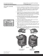
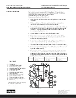
11.  Remove the cam by rotating it 90 degrees and carefully extracting it from 

the pump housing. Note the large pocket under the cam fits on the pressure 
control side of the pump housing (same side as the three seals on the hous-
ing flange). Figure 2

12.  Remove the front tapered roller bearing cone.

13.  If there is excessive wear or damage, remove the tapered roller bearing cup 

from the bottom of the housing.

14.  If completing a seal change or complete overhaul, turn the housing over and 

remove the snap ring and shaft seal from the housing. Note: do not reuse the 
shaft seal.

15.  If there is excessive wear on the port block bearing cup, cone, or both; re-

move the tapered roller bearing cup from the port block.

16.  If complete overhaul or rotation change, remove control piston and bias 

piston guides. The control piston and bias piston guides are installed with 
anerobic thread lock. Place the port block wih piston guides in oven at 163° 
C (325° F) 
NOTE: To prevent annealing of heat treated surfaces: DO NOT USE A 
TORCH TO HEAT PISTON GUIDES. 

Large Pocket

Pressure control

side of pump

060, 075, 100, 140 Pump Maintenance

PUMP DISASSEMBLY PROCEDURE 

(continued)

Summary of Contents for COMPAX P1 Series

Page 1: ...P1 PD Series 18cc to 140cc Medium Pressure Axial Piston Pumps Variable Displacement Service Information Bulletin HY28 2665 02 SVC EN Effective February 19 2015...

Page 2: ...ment are hereby offered for sale by Parker Hannifin Corporation its subsidiaries or its authorized distributor This offer and its accepteance are governed by the provisions stated in the detailed Offe...

Page 3: ...oded view 20 Parts list for 060 075 100 140 21 Electronic Control Exploded View 22 Parts list for Electronic Control 23 Case to inlet check valves 24 Volume stop 25 Seal and parts kits 26 27 L compens...

Page 4: ...and strength to assure free flow through the pump An undersize inlet line will prevent the pump from operat ing properly at full rated speed An undersize outlet line will cause back pressure and caus...

Page 5: ...steps Check for leaks in all lines especially in pump and motor inlet lines Make correct pressure adjustments Gradually increase speed Be alert for trouble as indicated by changes in sounds system sh...

Page 6: ...air trap cavitation in rotating group fluid too cold fluid too viscous fluid too heavy shaft speed to high inlet line too small inlet strainer too small inlet strainer too dirty operating altitude too...

Page 7: ...ffectiveness with chemical aging improper repair incorrect parts incorrect procedures dimensions finishes unwanted water in fluid condensation faulty breather strainer heat exchanger leakage faulty cl...

Page 8: ...L Counterclockwise Pump Series P1 Mobile PD Industrial Configuration M Mobile P1 S Industrial PD Mounting Ports S SAE A Pilot SAE Threaded Work Ports with SAE Aux Ports A SAE A Pilot Metric Work Port...

Page 9: ...ration M Mobile P1 S Industrial PD Mounting Ports S SAE B Pilot SAE Work Ports with SAE Aux Ports A SAE B Pilot Metric Work Ports with BSPP Aux Ports M ISO 100MM Pilot Metric Work Ports with Aux Ports...

Page 10: ...D Industrial Configuration M Mobile P1 S Industrial PD U Universal SAE Mounting Option S Only Mounting Ports S SAE B Pilot with SAE Threaded or Flange Work Ports with SAE Aux Ports A SAE B Pilot with...

Page 11: ...AN Pilot operated pressure limiter with ISO4401 interface SAE 4 Vent Port AL Pilot operated pressure limiter with Load sensing only available with T Torque Limiter option i e ALT AM Pilot operated pr...

Page 12: ...0 PSI 20 80 bar L0 Load sensing 145 04 435 11 PSI P 10 30 bar P with pressure limiter 1160 30 4061 05 PSI 80 280 bar L1 Load sensing 145 435 PSI P 10 30 bar P with pressure limiter 290 1450 PSI 20 100...

Page 13: ...haft SAE C C 17T 02 Keyed shaft SAE C C 38 1 04 Keyed shaft ISO DIN 40MM Dia 06 Splined shaft SAE C 14T Pump Series P1 Mobile PD Industrial Mounting Ports S SAE C Pilot SAE Flange Connection Ports wit...

Page 14: ...02 Keyed shaft SAE D 44 1 04 Keyed shaft ISO DIN 50MM Dia Mounting Ports S SAE D Pilot SAE Flange Connection Ports with SAE Aux Ports A SAE D Pilot BSPP Flange Connection Ports with BSPP Aux Ports M...

Page 15: ...mm 125 mm 125 mm 125 mm 180 mm SAE Keyed Shafts 19 1 A 25 1 BB 25 1 BB 32 1 C 32 1 C 38 1 CC 44 1 D ISO Keyed Shafts 20 mm 25 mm 25 mm 32 mm 32 mm 40 mm 50 mm SAE Spline Shafts 9T A 11T A 13T B 15T BB...

Page 16: ...ems Division Marysville Ohio USA Bulletin HY28 2665 02 SVC EN Medium Pressure Axial Piston Pumps P1 PD Maintenance 16 18cc 28cc Pump Exploded View 25 26 43 27 28 31 32 35 47 38 34 46 33 39 1 4 3 8 7 1...

Page 17: ...ems Division Marysville Ohio USA Bulletin HY28 2665 02 SVC EN Medium Pressure Axial Piston Pumps P1 PD Maintenance 17 45cc Pump Exploded View 25 26 43 27 28 31 32 35 47 38 34 46 33 39 1 3 41 4 8 7 14...

Page 18: ...0 Barrel hold down washer 22 3 787000 03E 94386 0 03E 95903 0 Barrel hold down pin 23 1 03E 94717 0 03E 94375 0 03E 94338 0 Barrel 24 1 787002 03E 94385 0 03E 94348 0 Spherical washer 25 1 786994 03E...

Page 19: ...Parker Hannifin Corporation Hydraulic Pump and Power Systems Division Marysville Ohio USA Bulletin HY28 2665 02 SVC EN Medium Pressure Axial Piston Pumps P1 PD Maintenance 19 Notes...

Page 20: ...ivision Marysville Ohio USA Bulletin HY28 2665 02 SVC EN Medium Pressure Axial Piston Pumps P1 PD Maintenance 20 Pump Exploded View 060 075 100 140 5 6 1 2 3 4 7 9 11 10 13 10 14 12 16 18 15 17 19 20...

Page 21: ...zes 19 1 356 65152 0 356 65144 0 356 65146 0 356 65147 0 Retaining ring internal 20 1 03E 94049 0 03E 93145 0 03E 93795 0 03E 93959 0 Barrel hold down spring 21 1 03E 94050 0 03E 93146 0 03E 93796 0 0...

Page 22: ...orporation Hydraulic Pump and Power Systems Division Marysville Ohio USA Bulletin HY28 2665 02 SVC EN Medium Pressure Axial Piston Pumps P1 PD Maintenance 22 Electronic Control Exploded View Torque to...

Page 23: ...40 85 1 789764 Seal 86 1 675 00904 0 O Ring Seal 87 1 108X4V O Ring boss plug 88 1 S13 40266 0 Check Valve 89 1 S2E 19182 5 External Servo Assembly 90 1 03E 95347 0 External servo manifold 91 1 S2E 19...

Page 24: ...ton Pumps P1 PD Maintenance 24 Case to Inlet Check Valve CASE TO INLET CHECK VALVE Item No Qty 018 028 045 060 075 100 140 Description 50 1 314 10002 0 314 10000 0 Hollow Set Screw 51 1 03E 94720 0 03...

Page 25: ...Screw 55 1 Order Kit Adjusting Screw Lock Nut 56 1 Order Kit Volume Stop Plug 57 1 Order Kit Volume Stop Plug O ring 58 1 Order Kit Backup Ring 59 1 Order Kit Volume Stop Rod O ring 60 1 Order Kit Vo...

Page 26: ...Thru Drive Couplings O ring 018 028 045 060 075 100 140 SAE A 9 Tooth S2E 19538 0 S2E 19364 0 03E 94942 0 03E 93278 0 03E 93278 0 03E 94274 0 03E 93947 0 695 00237 0 SAE A 11 Tooth S2E 19726 0 S2E 193...

Page 27: ...87 0K S2E 18491 0K CW Industrial PD w Ripple Chamber S2E 19207 0K S2E 19211 0K S2E 19126 0K CCW Industrial PD S2E 18713 0K S2E 19122 0K S2E 19070 0K S2E 18701 0K S2E 18484 0K S2E 18488 0k S2E 18492 0K...

Page 28: ...mber Port Rotation L0 80 280bar 1150 4000 psi L1 20 100 bar 300 1150 psi L2 80 280bar 1150 4000 psi L3 20 80 bar 300 1150 psi SAE CW S2E 19051 5T S2E 18245 5T S2E 18584 5 T N A CCW S2E 19053 5T S2E 18...

Page 29: ...1 ft lbs 13 1 Load Sense Compensator Spring cap O ring 14 1 Load Sense Compensator Piston backup ring 15 1 Load Sense Compensator Piston O ring 16 1 Load Sense Compensator Seal Piston 17 1 Load sense...

Page 30: ...Spring cap 115 7 N m 85 5 ft lbs 10 1 Adjusting screw 11 1 Adjusting screw Lock Nut 7 9 0 8 N m 70 7 in lbs 12 1 Socket set screw Loctite 242 3 4 0 4 N m 30 3 in lbs 13 4 Hex mounting screw 5 0 0 3 N...

Page 31: ...N A R70 2 R59 2 CCW Rotation CW Rotation Compensator Part Number Rotation AM AN AL AE AF CW S2E 18745 5T S2E 18743 5T S2E 19107 5T S2E 18747 5T S2E 18749 5T CCW S2E 18746 5T S2E 18744 5T S2E 19106 5T...

Page 32: ...pring seat Remove the o ring boss access plug on the opposite side of the compensator Remove the load sense compensa tor spool NOTE the load sense compensator spool and spring are not interchangeable...

Page 33: ...r spring assembly in the compensator body The rounded end of the spool should be installed first so it will contact the spring seat Install a new o ring on the hardened SAE boss fitting and place it i...

Page 34: ...he control valve For complete overhaul all o rings and seals should be discarded and replaced 1 Identify the pump from information on the data tag Figure 1 Figure 1 018 028 045 Pump Maintenance Pump d...

Page 35: ...e step 5 11 Remove the cam by rotating it 90 degrees and carefully extracting it from the pump housing Note the large pocket under the cam fits on the pressure control side of the pump housing same si...

Page 36: ...Size only NOTES Access plugs on end of compensator spool bores are hardened plugs Do not interchange with other plugs in the control For rotation change the complete compensator assembly will need to...

Page 37: ...ny marks beyond light polishing indicate that replacement is necessary Check the surface of the spherical area of the retainer plate and the spherical guide ball Inspect the back surface of the spheri...

Page 38: ...Shoe Flange Thickness 2 97 mm S2E 18415 0 Max End Play 0 07 mm Min Shoe Flange Thickness 3 98 mm S2E 184130 0 Max End Play 0 10 mm Min Shoe Flange Thickness 4 98 mm Measure OD in 3 places top middle a...

Page 39: ...Install internal retaining ring into the housing See drawing 3 If barrel hold down spring was removed during disassembly process install three pins to slots in barrel spline 45 Size only Petroleum jel...

Page 40: ...the hold down plate install the pistons into the barrel 14 Install the locating pin on the port block face 15 Apply Loctite Primer Grade T to guide threads and allow to dry Install unlubricated o ring...

Page 41: ...aring must face the outer wall of the housing Use Loctite Primer Grade T or other suitable primer on screws and mating threads in housing Apply Loctite 242 use sparingly to screw threads and install o...

Page 42: ...C D E F 045 SAE 045 ISO 028 SAE 028 ISO 018 SAE 018 ISO 0 05 0 00mm 0 002 0 000 in A B 0 05mm 0 002 in D C BLEND RADIUS POLISH O D 30 F DIA BORE E DIA Pump Model A B C D E F 018 01 02 04 Shafts 76 20...

Page 43: ...m in 0 8 7 7 1 0 0 0 2 0 0 7 7 8 7 0 25 40 1 00 T5 Rear Bushing Installation Tool mm in 29 92 1 178 89 75 3 53 50 80 2 00 19 05 0 75 38 10 1 50 101 60 4 00 A B 50 80 2 00 25 40 1 00 12 7 0 5 T5 Rear B...

Page 44: ...ith oil Refer to circuit below For units with L compensators connect a suitable pilot line from port X to the pump discharge pressure line down stream of the non compensating flow valve 4 Confirm dire...

Page 45: ...nsator set at 280 bar 30 lpm minimum 47 lpm minimum 77 lpm minimum When using the A series compensators increase compensated case leakage by 2 3 lpm TEST PROCEDURE PUMP WITH PRESSURE COMPENSATOR STEP...

Page 46: ...oting procedures previously listed do not solve the problem Caution Spring assemblies in the pump are normally set under high compression and bodily injury may occur if caution is not taken during dis...

Page 47: ...OTE For shaft change only no further disassembly is required Pro ceed to assembly procedure step 5 11 Remove the cam by rotating it 90 degrees and carefully extracting it from the pump housing Note th...

Page 48: ...e reworked if dimensions are with specifications listed in chart 1 3 The port plate can be lapped lightly if the face is only lightly scratched other wise it should be replaced 4 Examine the retainer...

Page 49: ...and bottom The measure ments should not vary by not more than 0 010 mm 0 0004 in Maximum material to be removed when lapping is 0 0051 mm 0 0002 in 26 Page 20 Piston and shoe assembly Sold in sets on...

Page 50: ...e seal bore Install the snap ring into the groove in the seal housing bore 3 Using installation tool T5 press the rear bearing cup into the port block Insure that the cup is seated firmly against the...

Page 51: ...mm 135 in 3 36 mm 1323 in 03E 93566 0 03E 94149 0 03E 93970 0 3 45 mm 136 in 3 51mm 138 in 3 44 mm 1354in 03E 93567 0 03E 94150 0 03E 93971 0 3 52 mm 139in 3 62 mm 142 in 3 52 mm 1386 in 03E 93568 0 0...

Page 52: ...Install the spherical guide ball into the hold down plate While holding the guide ball against the hold down plate install the pistons into the barrel Chart 3 Pump Control and Bias Guide Torque 060 1...

Page 53: ...thin film of clean oil on cam bearing surfaces Install cam in housing The cam must be tilted to permit entry into the housing Figure 2 NOTE The large pocket on the bottom surface of the cam must be o...

Page 54: ...mm 1 00 in 10 53 04 mm 2 088 in 44 48 mm 1 751 in 140 ISO 213 0 004201 114 mm 4 50 in 76 2 mm 3 00 in 22 4 mm 0 88 in 15 53 04 mm 2 088 in 50 04 mm 1 970 in Pump Model Part Number A B C D 060 075 213...

Page 55: ...mm 3 515 in 15 Pump Model Part Number A B C 060 075 213 0 004193 53 8 mm 2 120 in 48 7 mm 1 918 in 12 100 213 0 004205 65 1 mm 2 562 in 59 3 mm 2 335 in 15 140 213 0 004198 71 1 mm 2 80 in 65 1 mm 2 5...

Page 56: ...h oil Refer to circuit below For units with L compensators connect a suitable pilot line from port X to the pump discharge pressure line down stream of the non compensating flow valve 4 Confirm direct...

Page 57: ...with compensator set at 280 bar 99 lpm min 126 lpm min 165 lpm min 233 lpm min When using the A series compensators increase compensated case leakage by 2 3 lpm TEST PROCEDURE PUMP WITH PRESSURE COMPE...

Page 58: ...N REQUIRED VALUE MEASURED VALUE 1 Set the pump speed to 1800 RPM 1800 rpm 2 Record input oil temperature 43 54 C 110 130 F 3A Set output load prssure to 50 2 bar 725 30 psi n a n a 3B Adjust throttle...

Page 59: ...F 1 8 viscosity cSt x 1 0 mm2 sec mm2 sec x 1 0 cSt SSU cSt x 4 25 14 20 cSt 99 SSU FLUID POWER FORMULAS Pump input torque lbs in pressure psi x displacement in3 rev 2 x mech eff Pump input power hp...

Page 60: ...Parker Hannifin Corporation Hydraulic Pump and Power Systems Division Marysville Ohio USA Bulletin HY28 2665 02 SVC EN Medium Pressure Axial Piston Pumps P1 PD Maintenance 60 Notes...

Page 61: ...0 L1 L2 and L3 compensator moved note from item number 6 to item number 4 Updated exploded view on C0 and C1 compensator Updated part number on CCW AL control Added additional information to port adap...

Page 62: ...Parker Hannifin Corporation Hydraulic Pump and Power Systems Division Marysville Ohio USA Bulletin HY28 2665 02 SVC EN Medium Pressure Axial Piston Pumps P1 PD Maintenance 62 Notes...

Page 63: ...n apparatus belonging to Seller which is utilized in the manufacture of the Products even if such apparatus has been specially converted or adapted for such manufacture and notwithstanding any charges...

Page 64: ...Pump and Power Systems Division 14249 Industrial Parkway Marysville OH 43040 USA phone 937 644 4435 fax 937 642 3639 www parker com hps Bulletin HY28 2665 02 SVC EN Effective 02 2015 2015 Parker Hann...

Reviews: