background image


Device

 description 

Multi-axis devices 


26 

192-120148N5 June 2011


3.2 

Mounting and dimensions 


During operation, the device radiates heat (power loss). Please provide for a 

sufficient mounting distance below and above the device in order to ensure free 

circulation of the cooling air. Please do also respect the recommended distances of 

other devices. Make sure that the mounting plate is not exhibited to other 

temperature influences than that of the devices mounted on this very plate. The 

devices must be mounted vertically on a level surface. Make sure that all devices 

are sufficiently fixed.  


3.2.1. 

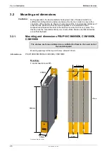
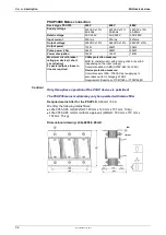
Mounting and dimensions PSUP10/C3M050D6, C3M100D6, 

C3M150D6 

The devices are force-ventilated via a ventilator fan fixed to the lower part of 

the heat dissipator! 

Mounting spacing: At the top and below: at least 100mm  


Information on 

PSUP10D6/C3M050D6, C

3M100D6, C3M150D6 


2 socket head screws M5 

Mounting: 

50mm

360mm

263mm


46mm

50,5mm

400mm

90°


Tolerances: DIN ISO 2768-f 


Ventilation: 

Summary of Contents for Compax3M Series

Page 1: ...n Manual Multi axis devices Paper version Release R09 20 C3Manager Compax3M Unterlagen Software user guides tools manuels tools Compax3 DVD english deutsch fran ais Compax3M Installations Handbuch deu...

Page 2: ...annifin GmbH registered office Bielefeld HRB 35489 Gesch ftsf hrung Dr Gerd Scheffel G nter Schrank Christian Stein Kees Veraart Aufsichtsratsvorsitzender Hansgeorg Greuner Headquarters Parker Hannifi...

Page 3: ...C3 ServoManager software tool is also functioning independently from the Parker Integrated Engineering Tool After the installation of the ServoManager you can copy the desired Online help system with...

Page 4: ...ace USB For the installation of the software you need administrator authorization on the target computer Note Several applications running in parallel reduce the performance and operability Especially...

Page 5: ...ou can read the device type of the connected device Online Device Identification or select a device type Device Selection Wizard Then you can double click on Configuration to start the configuration w...

Page 6: ...19 2 7 3 Current on the mains PE leakage current 20 2 7 4 Supply networks 21 2 8 EC declaration of conformity Compax3M 22 2 9 EC declaration of conformity PSUP 23 3 Device description 24 3 1 Installa...

Page 7: ...odule 35 3 6 7 Motor motor brake Compax3M axis controller 37 3 6 8 Safety technology option for Compax3M axis controller 38 3 7 Communication interfaces 38 3 7 1 Communication Compax3M 38 3 8 Signal i...

Page 8: ...mpax3M300D6 supplement PSUP10D6 mains module PSUP20D6 mains module PSUP30D6 mains module 2 2 Scope of delivery The following items are furnished with the device Manuals Installation manual German Engl...

Page 9: ...nput Input supply data Power Output Output data 5 Designation of the feedback system F10 Resolver F11 SinCos Single or Multiturn F12 Feedback module for direct drives 6 Device interface I10 Analog ste...

Page 10: ...10 10kW D6 Designation nominal supply 3 Configuration and parameterization interface USB USB connection 4 Options Mxx I O extension 5 Unique number of the particular device 6 Date of factory test 7 No...

Page 11: ...ns materials that fall under the special disposal regulation from 1996 which corresponds to the EC directory 91 689 EEC for dangerous disposal material We recommend to dispose of the respective materi...

Page 12: ...red with 400VAC axis controllers and PSUP mains module If the device was stored longer than one year the intermediate capacitors must be re formed Forming sequence Remove all electric connections Supp...

Page 13: ...rpose 2 5 2 Safety conscious working This device may be operated only by qualified personnel Qualified personnel in the sense of these operating instructions consists of Persons who by virtue to their...

Page 14: ...ective lead The devices are equipped with high voltage DC condensers Before removing the protective cover the discharging time must be awaited After switching off the supply voltage it may take up to...

Page 15: ...device or multi axis devices via L1 and L2 on the PSUP mains module 2 6 Warranty conditions The device must not be opened Do not make any modifications to the device except for those described in the...

Page 16: ...esent on the device connections even if they are not wired Please respect the specifications of the manual especially the technical characteristics mains connection circuit breakers output data ambien...

Page 17: ...ox depends on the motor type 80m Corresponding to the specifications of the terminal clamp with a temperature range of up to 60 C Signal lines and power lines should be installed as far apart as possi...

Page 18: ...s according to EN 61800 3 In a domestic area this product can cause radio frequency disturbance in which case the user may be required to implement appropriate remedial measures Warning Autoryzowany d...

Page 19: ...f field installed conductors shall be at least 60 C Use copper lines only Please use the cables described in the accessories chapter they feature a temperature rating of at least 60 C Maximum Surround...

Page 20: ...ties of the motor cable and of the motor windings Due to the high clock frequency of the power output stage the leakage currents do have high frequency components Please check if the FI protection swi...

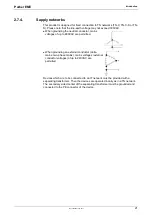
Page 21: ...s voltages of up to 480VAC are permitted When grounding an external conductor delta mains two phase mains mains voltages external conductor voltages of up to 240VAC are permitted Devices which are to...

Page 22: ...Introduction Multi axis devices 22 192 120148N5 June 2011 2 8 EC declaration of conformity Compax3M...

Page 23: ...Parker EME Introduction 192 120148N5 June 2011 23 2 9 EC declaration of conformity PSUP...

Page 24: ...device utilization the axis controller with the highest power is placed directly at the right of the mains module e g first the device type with high utilization at the right of this the same device t...

Page 25: ...er against to the left and tighten screws Proceed accordingly for all adjacent axis controllers in the combination Max tightening torque 1 5Nm Close all protective covers The protective covers must la...

Page 26: ...t exhibited to other temperature influences than that of the devices mounted on this very plate The devices must be mounted vertically on a level surface Make sure that all devices are sufficiently fi...

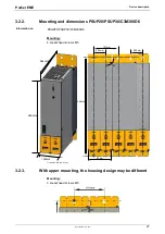
Page 27: ...imensions PSUP20 PSUP30 C3M300D6 Information on PSUP20 PSUP30 C3M300D6 4 socket head screws M5 Mounting 100mm 360mm 263mm 96mm 400mm 90 50 5mm 50 5mm 101mm Tolerances DIN ISO 2768 f 3 2 3 With upper m...

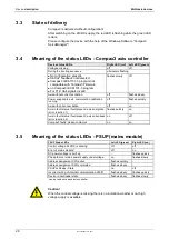
Page 28: ...alibration running off flashes quickly Axis with current excitation off on Axis in fault status fault present axis energized error reaction 1 flashes quickly on Axis in fault status fault present axis...

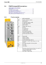
Page 29: ...0 LED2 X9 X3 S1 LED1 S24 LED4 X24 X23 X14 1 P M P Mains module PSUP LED1 Status LEDs Mains module S1 Basic address X3 Configuration interface USB X9 Supply voltage 24VDC M Axis controller LED2 Status...

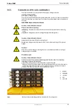
Page 30: ...res 70 C P Mains module PSUP X40 Ballast resistor X41 Mains supply VAC PE 1 Central ground connection for the axis system with 10mm2 to the ground screw on the housing 4 Fan M Axis controller X43 Moto...

Page 31: ...Risk of Electric Shock Always switch devices off before wiring them Dangerous voltages are still present until 10 min after switching off the power supply Caution When the control voltage is missing t...

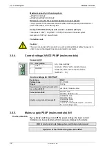
Page 32: ...24VDC PSUP mains module Connector X9 Pin Designation Line cross sections minimum 0 5mm2 with conductor sleeve maximum 6mm2 with conductor sleeve AWG 20 10 1 24 V 2 GND24V Control voltage 24 VDC PSUP...

Page 33: ...25A in accordance with UL category DIVQ Recommendation ABB S203UP K25 480VAC Mains connection PSUP20D6 Device type PSUP20 230V 400V 480V Supply voltage 230VAC 10 50 60Hz 400VAC 10 50 60Hz 480VAC 10 50...

Page 34: ...n line are required Cable protection measure MCB K characteristic with a rating of 63A 4xxVAC depending on the input voltage Recommendation ABB S203P K63 440VAC Device protection measure Circuit break...

Page 35: ...angerous voltages are still present until 10 min after switching off the power supply 3 6 6 Braking resistor temperature switch PSUP mains module The energy generated during braking operation must be...

Page 36: ...nection of a braking resistor on PSUP mains module Axis system 1615 F are sufficient Minimum line cross section 1 5 mm2 Maximum line length 2 m Maximum intermediate circuit voltage 810 VDC Switch on t...

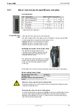
Page 37: ...to the Compax3 housing Use the cable clamps shield connecting terminals furnished with the device The shield of the cable must also be connected with the motor housing The fixing via plug or screw in...

Page 38: ...0 3 6 8 Safety technology option for Compax3M axis controller Connector X14 Pin Description 1 STO1 24VDC 2 STO GND GND 3 STO2 24VDC 4 STO GND GND Note If the Compax3M axis controller features a safety...

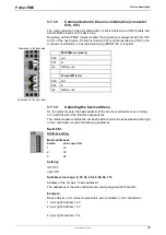
Page 39: ...use Compax3M axis X30 out X31 in res factory use 3 7 1 3 Adjusting the basic address On the mains module the basic address of the device combination is set in steps of 16 with the aid of the first th...

Page 40: ...e axis controller is stored in object O110 1 C3plus Switch_DeviceFunction and can be evaluated with the aid of a program Function settings for T30 and T40 This helps realize a more simple function sel...

Page 41: ...ted at the same time as X15 on Compaxx3M Resolver cables can be found in the accessories chapter of the device description SinCos cables can be found in the accessories chapter of the device descripti...

Page 42: ...max 10V 10 Ain1 analog input 14Bits max 10V 11 Ain0 analog input 14Bits max 10V 12 Input direction RS422 5V level B input simulation 13 factory use N input simulation DATA 14 factory use N input simul...

Page 43: ...pecific assignment in the online help which can be opened from the Compax3 ServoManager Maximum capacitive loading of the outputs 30nF max 2 Compax3 inputs 3 8 3 1 Connection of the digital Outputs In...

Page 44: ...uit rating Measure for line and device protection MCB miniature circuit breaker K characteristic 25A in accordance with UL category DIVQ Recommendation ABB S203UP K25 480VAC Mains connection PSUP20D6...

Page 45: ...y JFHR2 Requirement Bussmann 170M1368 or 170M1568D Control voltage 24 VDC PSUP Device type PSUP Voltage range 21 27VDC Ripple 0 5Vpp Requirement according to safe extra low voltage SELV yes class 2 ma...

Page 46: ...kVA 6 66kVA 10kVA 20kVA Switching frequency 8kHz 8kHz 8kHz 8kHz Power loss for In 70W 90W 120W 270W Electrical turning frequency for pulse current f 5 Hz with an electrical turning frequency of f 5 Hz...

Page 47: ...K Stegmann Absolute position up to 4096 motor revolutions For example SRS50 SRM50 SKS36 SKM36 SEK52 SEK52 SEL52 SEK37 SEL37 SEK160 SEK90 higher values on request Special encoder systems for direct dri...

Page 48: ...ication plate Insulation requirements Enclosure rating Protection class in accordance with EN 60664 1 Protection against human contact with dangerous voltages In accordance with EN 61800 5 1 Overvolta...

Page 49: ...l Category 3 PL e according to table 4 in EN ISO 13849 1 this corresponds to SIL 3 PFHd 4 29E 8 Ambient conditions PSUP Compax3M General ambient conditions In accordance with EN 60 721 3 1 to 3 3 Clim...

Page 50: ...ed harmonized EC norms EC low voltage directive 2006 95 EG EN 61800 5 1 Standard for electric power drives with settable speed requirements to electric safety EN 60664 1 isolation coordinates for elec...

Page 51: ...2 EC declaration of conformity PSUP 23 F Front connector 29 G General hazards 13 I Installation instructions Compax3M 24 Introduction 8 L LEDs 28 Level 43 M Mains supply PSUP mains module X41 32 Meani...

Page 52: ...y conditions 15 Wiring of analog interfaces 42 With upper mounting the housing design may be different 27 X X11 42 X12 43 X13 41 Autoryzowany dystrybutor Parker 53 012 Wroc aw ul Wy cigowa 38 tel 71 f...

Reviews: