Device
description
Multi-axis devices
36
192-120148N5 June 2011
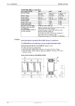
Braking operation PSUPxxD6 (mains module)
Device type
PSUP10
PSUP20
PSUP30
Capacitance / storable
energy
550 µF/
92 Ws at 400 V
53 Ws at 480 V
1175 µF/
197 Ws at 400 V
114 Ws at 480 V
1175 µF/
197 Ws at 400 V
114 Ws at 480 V
Minimum braking-
resistance
27
Ω
15
Ω
10
Ω
Recommended nominal
power rating
500 ... 1500 W 500 ... 3500 W
500 ... 5000 W
Pulse power rating for 1s
22 kW
40 kW
60 kW
Maximum permissible
continuous current
13 A
15 A
15 A
PSUP10: 2400 µF
Maximum capacity in the axis system:
PSUP20 & PSUP30: 5000 µF
100 µF per kW of the temporal medium value of the total power (transmi
power dissipation) in the axis system
Reference value for the required capacity in an axis system
Example: PSUP20 (1175 µF) with one axis controller (440 µF)
Total power 15 kW, 100 µF/kW => 1500 µF required in the axis system.
Connection of a braking resistor on PSUP (mains module)
Axis system: 1615 µF are sufficient.
Minimum line cross section:
1.5 mm
2
Maximum line length:
2 m
Maximum intermediate circuit voltage:
810 VDC
Switch-on threshold:
780 VDC
Hysteresis
20 VDC
Braking operation Compax3MxxxD6 (axis controller)
Device type
Compax3
M050
M100
M150
M300
Capacity/
storable energy
110µF/
18Ws at 400V
10Ws at 480V
220µF/
37Ws at 400V
21Ws at 480V
220µF/
37Ws at 400V
21Ws at 480V
440µF/
74Ws at 400V
42Ws at 480V
3.6.6.1
Temperature switch PSUP (mains module)
Connector X40 Pin T1R, T2R
Temperature monitoring:
The temperature switch (normally closed contact) must be connected, unless an
error message will be issued.
Temperature switch/relay
No galvanic separation, the temperature sensor (normally closed contact) must
comply with the safe separation according to EN 60664.
If there is no temperature monitoring due to the connected braking resistor, the
T1R and T2R connections must be connected by a jumper.
Caution!
Without temperature monitoring, the braking resistor might be destroyed.

