Parker EME
Device description
192-120148N5 June 2011
39
3.7.1.2
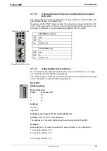
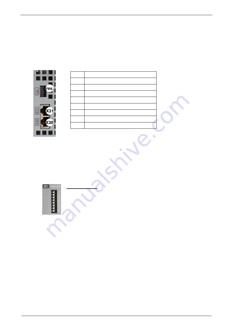
Communication in the axis combination (connector
X30, X31)
The communication in the axis combination is implemented via a SSK28 cable and
double RJ45 sleeves on the device top.
Beginning with the PSUP (mains module) the connection is always made from X30
to X31 of the next device. On the first device (X31) and the last device (X30) in the
multi-axis combination, a bus terminati
on plug (BUS07/01) is required.
Orientation to the back side
Orientation to the front plate
PSUP (Mains module)
X30
out
X31
in
res.
factory use
Compax3M (axis)
X30
out
X31
in
res.
factory use
3.7.1.3
Adjusting the basic address
On the mains module, the basic address of the device combination is set in steps
of 16 with the aid of the first three dip switches.
The mains module contains the set basic address while the axes placed at the right
in the combination contain the following addresses.
Switch S1
Basic addresses
Address setting
Switch
Value upon ON
1
16
2
32
3
64
Settings:
left: OFF
right: ON
Settable value range: 0, 16, 32, 48, 64, 80, 96, 112
Address of the 1st axis = basic 1
The addresses of the axis controllers are newly assigned after PowerOn.
Example:
Basic address = 48; mains module with 6 axis controllers in the combination
1. Axis right: Address = 49
2. Axis right: Address = 50
...
6. Axis right: Address = 54

