1 1 8
APEX615n Installation Guide
Within the cabinet itself, all the motor cables should lie in the same trunking as far as
possible. They must be kept separate from any low-level control signal cables. This applies
particularly where the control cables are unscreened and run close to the drive or other sources
of electrical noise.
Motor Feedback
Cables
Feedback devices such as encoders, tachometers, Hall effect sensors, and resolvers also require
the use of high-quality braided screen cable. If it is necessary to replace the standard feedback
cable, select a braided screen cable that matches the gage of the devices original cable and
attach as close to the transducer as possible. Avoid complex and bulky connections that can
cause degradation in feedback signal quality. If possible, use in-line cable splicing techniques,
and cover the splice point with heat-shrink tubing. Remove a section of the braided shield
cable’s insulation to expose the braid, and tie the braid to earth using the same P-clip 360
°
bond as shown in Figure 2. Differential signals should use twisted pair cable to minimize
magnetic coupling. At the receiving end, fit a ferrite absorber over the feedback cable before
wiring the connector, then P-clip the braid to a suitable ground, (metal back-plane of drive
mounting panel, or earth point of device that receives the feedback), Figure 4.
Servo Motors
It is preferable to use motors with screw terminations whenever possible. If flying-lead motors
are used, it is important that the unscreened leads are converted into a braided-screen cable
within 4 inches (10cm) of the motor body. A separate terminal box may be used for this
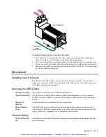
purpose but the braided cable screen must be properly strapped to the motor body.
Servo Motor
Motor and Resolver
Cables
Safety Earth
Cable
(green/yellow)
Figure 3: Servo Motor Detail - P-Clip, Safety Earth
Artisan Technology Group - Quality Instrumentation ... Guaranteed | (888) 88-SOURCE | www.artisantg.com


