7 0
APEX615n Installation Guide
Tachometer Output Calibration
Use the Tachometer Output Calibration potentiometer to precisely calibrate the APEX615n
Controller/Drive's tachometer output, while monitoring the actual tachometer output at the
Tach Out pin on the Drive Auxiliary connector. For example, a commanded velocity of 4000
rpm should produce Tach Out signal of 4 volts. Adjust the potentiometer until the Tach Out
signal is measured at 4 volts.
Aligning the Resolver
You can operate the APEX615n in alignment mode if you need to align your motor’s resolver.
This is a rarely used feature. Resolvers on APEX Series motors are aligned at the factory, and
need no further adjustments. It is usually not necessary to align resolvers on other
manufacturer’s motors.
However, if you need to replace the resolver on a motor, if you have a motor with unknown
characteristics, or if poor speed/torque performance leads you to suspect that the resolver is out
of alignment, you can follow the procedure below.
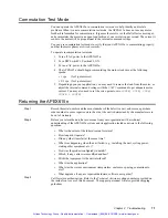
To align the resolver, perform the following steps.
1. Turn OFF AC power to the APEX615n and remove the load from the motor. The
motor’s shaft must be free to turn.
2. Turn DIP Switch#3, position 2, ON. Turn ON AC power to the APEX615n.
3. Set all servo gains to zero
[SGPØ, SGIØ, SGVØ, SGAFØ, & SGVFØ]
.
4. For 2-pole-pair motor: Set offset voltage to negative one half volt
[SOFFS-Ø.5]
.
For 3-pole-pair motor: Set offset voltage to positive one half volt
[SOFFSØ.5].
5. Enable the APEX615n drive
[DRIVE1]
. The motor shaft should turn and lock into
position. If it does not lock into position, increase
SOFFS
slightly. Use only enough
current in the motor to maintain holding torque. Excess current may cause motor
overheating.
6. With the motor shaft locked in the alignment position, loosen the screws on the
resolver so that it can turn.
7. Slowly rotate the resolver while you observe the APEX615n’s front panel LEDs. When
the resolver is in the correct position, both the
MOTOR FAULT
and the
I2T LIMIT
LEDs
will be illuminated. When the resolver is close to the correct position, only one of the
LEDs will be illuminated. When the rotor is not close to the correct position, no LED
will be illuminated.
8. With the resolver in the correct position (both LEDs illuminated), tighten the screws on
the resolver so that its case can no longer rotate.
9. Turn off AC power, and turn DIP Switch#3, position 2, OFF.
Resolver alignment is now complete. You can resume normal operations.
While the APEX615n is in alignment mode, it commutates current as follows:
•
For 2–pole motors:
Current out of Phase B and into Phase C
•
For 3–pole motors:
Two equal currents out of Phases B and C. Both
currents into Phase A
Artisan Technology Group - Quality Instrumentation ... Guaranteed | (888) 88-SOURCE | www.artisantg.com


