7 4
APEX615n Installation Guide
Load
Drive
Motor
Load
Command
Digital
Control
Algorithm
Control
Signal
Offset
Analog Command =
Control Offset
Drive
Closed Loop System
SOFFS
Offset
Drive Command = Offset
Servo Algorithm Disabled
Feedback Data
Motor
Feedback Device:
Resolver, Encoder,
or ANI Input
Feedback Device:
Resolver, Encoder,
or ANI Input
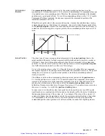
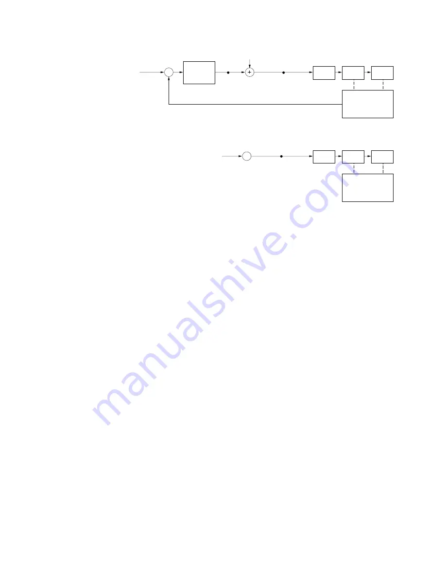
Internally, the APEX615n has two main sections—a controller section and a drive section.
The controller accepts a motion command, and uses its digital control algorithm to calculate a
digital control signal. This digital value is sent from the digital signal processor (DSP ) to the
digital-to-analog converter (DAC). The DAC has an analog output range of -10V to +10V.
The DAC’s output, an analog control signal, is sent to the APEX615n’s drive section. The
drive produces motor current that is proportional to the voltage level of the analog signal.
It is possible that the digital control signal calculated by the control algorithm can exceed the
±
10V limit. When this happens, the analog output will stay, or saturate, at the maximum
limit until the position error changes such that the control algorithm calculates a control
signal less than the limit. This phenomenon of reaching the output limit is called
controller output saturation. When saturation occurs, increasing the gains does not
help improve performance since the DAC is already operating at its maximum level.
Position Variable Terminology
In a servo system, there are two types of time-varying (value changes with time) position
information used by the controller for control purposes: commanded position and actual
position. You can use this information to determine if the system is positioning as you
expect.
Artisan Technology Group - Quality Instrumentation ... Guaranteed | (888) 88-SOURCE | www.artisantg.com


