5
OEM650/OEM650X • INSTALLATION
WARNING
The drive and motor should be mounted to a heatsink. Drive mounting does not affect
the following tests, but if you operate the OEM650/OEM650X for extended periods
without proper mounting, it will damage the drive and/or motor. When you complete
the quick tests, remove power to the drive.
Perform installation and test procedures in a properly grounded
environment. Compumotor recommends the use of a grounding
strap.
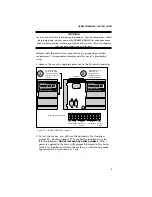
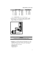
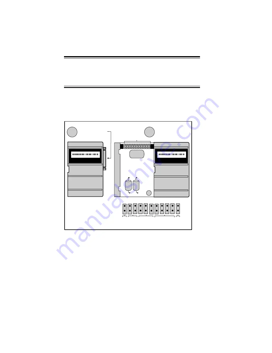
1. Remove the cover by applying pressure to the 25-pin D connector.
To remove cover,
push the 25-pin D
connector in while
holding the sides of
the unit.
11
10
9
8
7
6
5
4
3
2
1
Jumpers
A
When the cover is
removed, the
jumpers will be
visible at the upper
portion of the unit.
B
Auto
Test
Auto
Standby
Motor
Waveform
Shape
Motor
Resolution
Motor
Current
Range
Enlarged view of jumpers
Compumotor
5500 Business Park Dr.
Rohnert Park, CA 94928
Prod: Ø571Ø2-2-6-Ø17-Ø1Ø
Made In USA
Compumotor
5500 Business Park Dr.
Rohnert Park, CA 94928
Made In USA
Prod: Ø571Ø2-2-6-Ø17-Ø1Ø
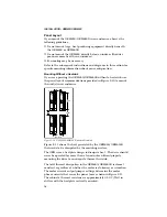
Figure 2-1. OEM650/OEM650X Jumpers
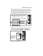
2. To test the system, you will use the Automatic Test function,
jumper
11
.
Remove jumper
11
to enable the function (save for
later installation).
Do not remove any other jumpers
. When
power is applied to the drive with jumper
11
removed, the Auto-
matic Test function will rotate the motor in an Alternating mode
approximately 6 revolutions at 1 rps.


