9
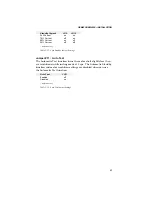
OEM650/OEM650X • INSTALLATION
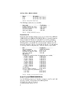
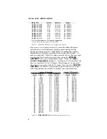
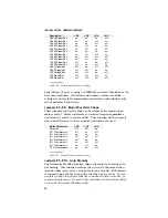
Jumper #1 Installed
Jumper #1 Removed
Current Resistance
Current Resistance
Current Resistance
(Amps)
(Ohms)
(Amps)
(Ohms)
(Amps)
(Ohms)
2.0
0
Ω
1.3
7.32 k
Ω
0.7
0
Ω
1.9
787
Ω
1.2
8.87 k
Ω
0.6
2.21 k
Ω
1.8
1.62 k
Ω
1.1
10.7 k
Ω
0.5
5.36 k
Ω
1.7
2.49 k
Ω
1.0
13.0 k
Ω
0.4
10.0 k
Ω
1.6
3.57 k
Ω
0.9
15.4 k
Ω
0.3
16.2 k
Ω
1.5
4.64 k
Ω
0.8
18.2 k
Ω
0.2
27.4 k
Ω
1.4
5.90 k
Ω
0.7
21.5 k
Ω
Table 2-9.
OEM350/350X
Resistor Selection for Motor Current
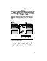
6. Connect a 24VDC - 75VDC power supply to
VDC+
and
VDC
-
.
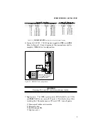
Refer to Figure 2-5 for a diagram of this connection and the
complete OEM650 test configuration.
OEM
s
e
r
i
e
s
REMOTE
REF
CURRENT
DUMP
VDC+
VDC-
A+
A-
B+
B-
POWER
FAULT
Power
-
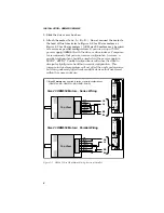
Refer to Figures 2-2 and
2-3 for specific motor
wiring instructions
OEM
Series
Motor
Figure 2-5. OEM650 Test Configuration
WARNING
Reversing VDC+ and VDC- can seriously damage the drive.
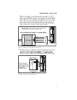
7. Apply power. The OEM’s green power LED should be on. If the
red
FAULT
LED is on, consult
Chapter 4, Troubleshooting
.
After
verifying that the motor moves CW and CCW, turn off power.
❐
Disconnect cables and resistor.
❐
Snap off cover.
❐
Install jumper
11
.
❐
Replace cover.

