INSTALLATION • OEM650/OEM650X
12
Handshaking is not supported. Terminals should be set for full
duplex mode.
3. Apply power. The OEM’s green power LED should be on. If the
red
FAULT
LED is on, consult
Chapter 4, Maintenance & Trouble-
shooting
.
This test assumes that your indexer’s motor resolution is set to
25,000 steps/rev. This is the default motor resolution setting
for the OEM650X
.
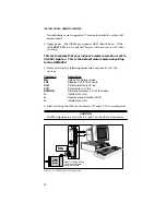
4. Enter and run the following command sequence to test the
system.
Command
Description
MN
Sets unit to Normal mode
LD3
Disables CW & CCW Limits
A1Ø
Set acceleration to 10 rps
2
V1Ø
Set velocity to 10 rps
D25ØØØ
Set move distance to 1 CW revolution
G
Initiate move (Go)
H
Reverse move direction (CCW)
G
Initiate move (Go)
5. After verifying that the motor moves CW and CCW, turn off power.
CAUTION
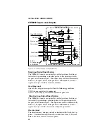
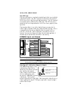
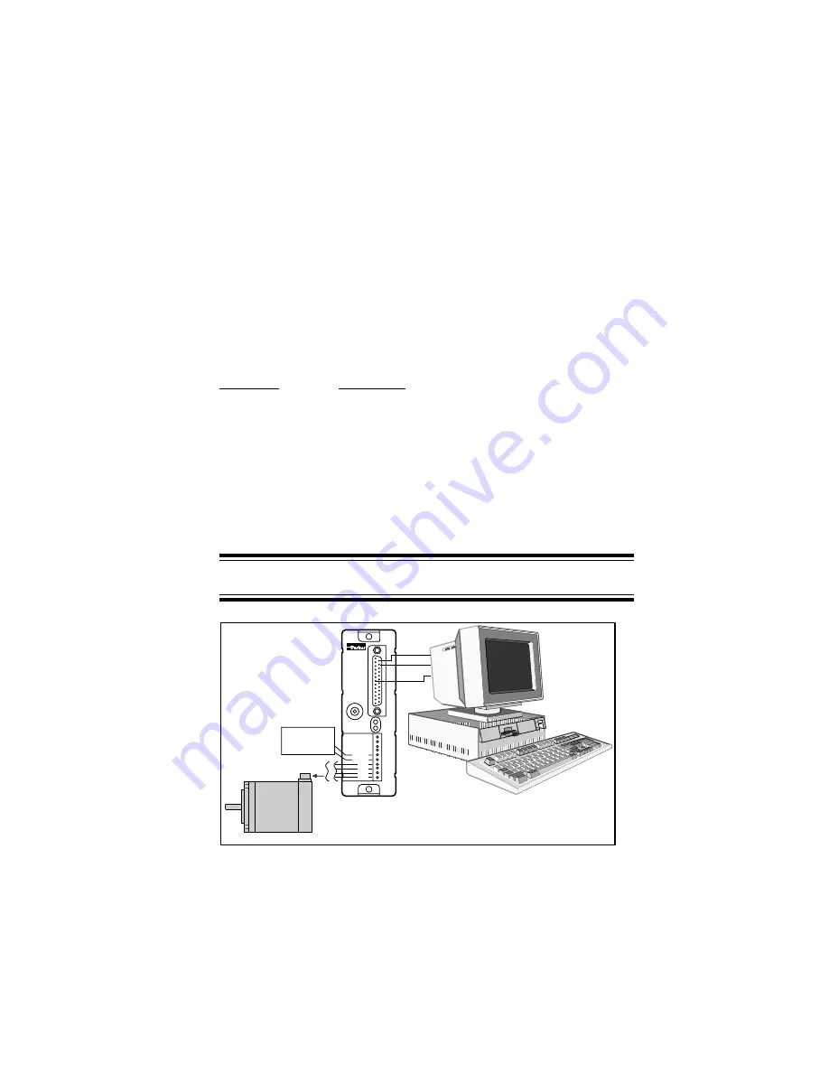
RS-232C signals are not on pins 2, 3, and 7 on the 25-pin D connector.
OEM
s
e
r
i
e
s
REMOTE
REF
CURRENT
DUMP
VDC+
VDC-
A+
A-
B+
B-
POWER
FAULT
Power
-
Refer to Figures 2-2 and
2-3 for specific motor
wiring instructions
OEM
Series
Motor
14 Tx
7 GND
15 Rx
Rx
Tx
GND
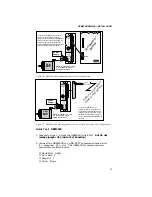
Figure 2-8. OEM650X Test Configuration

