INSTALLATION • OEM650/OEM650X
14
Panel Layout
If you mount the OEM650/OEM650X in an enclosure, observe the
following guidelines:
❏
Do not mount large, heat-producing equipment directly beneath
the OEM650 or OEM650X.
❏
Do not mount the OEM650 directly below an indexer (the drive
produces more heat than an indexer).
❏
Fan cooling may be necessary.
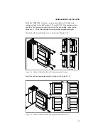
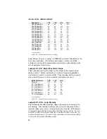
Refer to the subsequent instructions and diagrams in this section for
specific mounting information about your configuration.
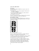
Mounting Without a Heatsink
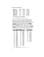
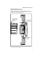
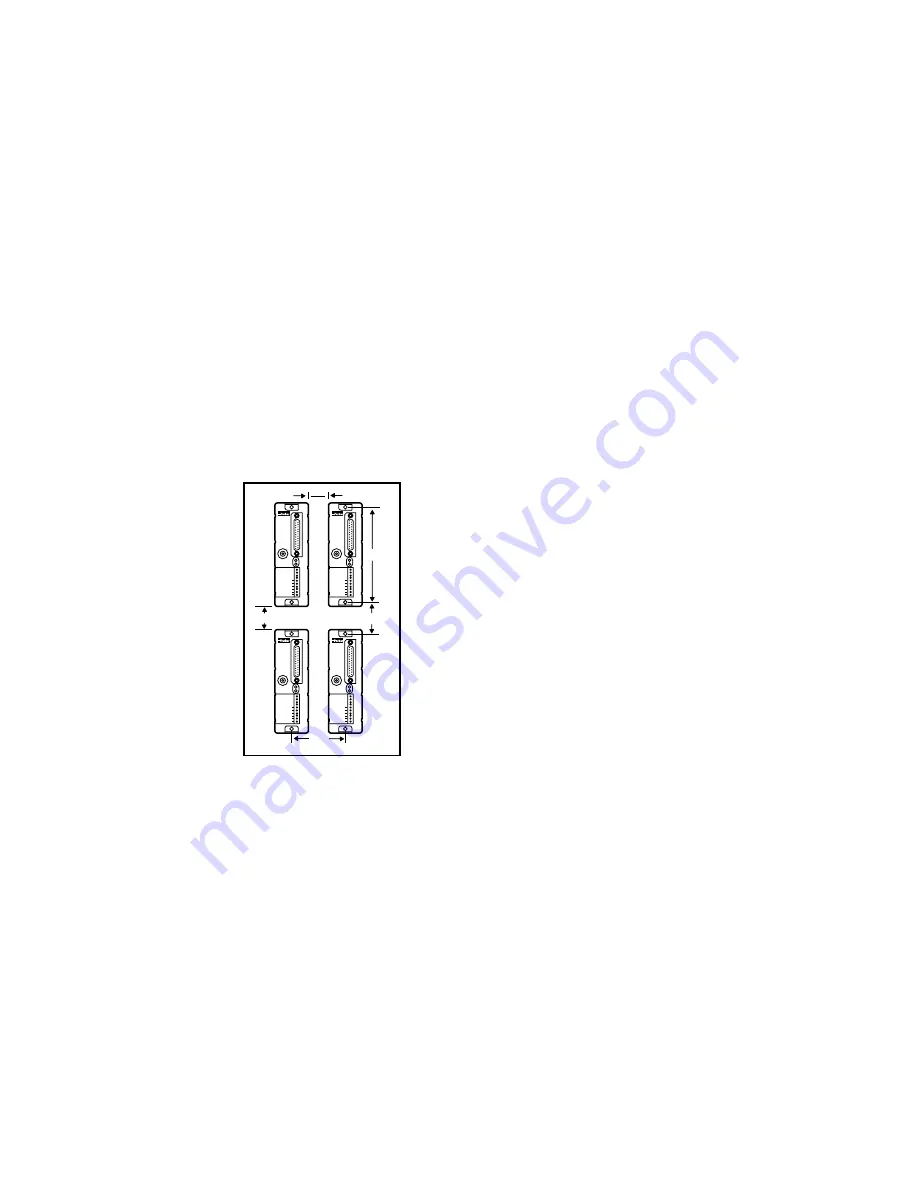
If you are operating the OEM650/OEM650X without a heatsink, use
the panel layout recommendations provided in Figure 2-10 to mount
the unit(s) in an enclosure.
OEM
s
e
r
i
e
s
REMOTE
REF
CURRENT
DUMP
VDC+
VDC-
A+
A-
B+
B-
POWER
FAULT
OEM
s
e
r
i
e
s
REMOTE
REF
CURRENT
DUMP
VDC+
VDC-
A+
A-
B+
B-
POWER
FAULT
OEM
s
e
r
i
e
s
REMOTE
REF
CURRENT
DUMP
VDC+
VDC-
A+
A-
B+
B-
POWER
FAULT
OEM
s
e
r
i
e
s
REMOTE
REF
CURRENT
DUMP
VDC+
VDC-
A+
A-
B+
B-
POWER
FAULT
0 . 3 7 5 "
4 . 6 5 "
2 . 3 5 "
2 "
M i n i m u m
2 "
Figure 2-10. OEM650/OEM650X Without a Heatsink
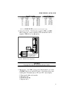
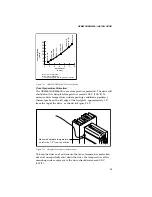
Figure 2-11 shows the heat generated by the OEM650/OEM650X
that needs to be dissipated by the mounting surface.
The OEM uses a heatplate design to dissipate heat. The drive should
never be operated for more than a few minutes without properly
mounting the drive to an adequate thermal heatsink.
The total thermal dissipation in the OEM650/OEM650X is almost
constant, regardless of whether the motor is stationary or in motion.
The motor current output jumper settings determine the motor
phase currents that cause the power losses shown in Figure 2-11.
The cabinet's thermal resistance is approximately 0.35°C/Watt in
still air with the heatplate vertically oriented.


