17
OEM650/OEM650X • INSTALLATION
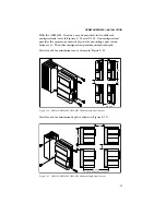
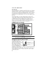
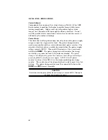
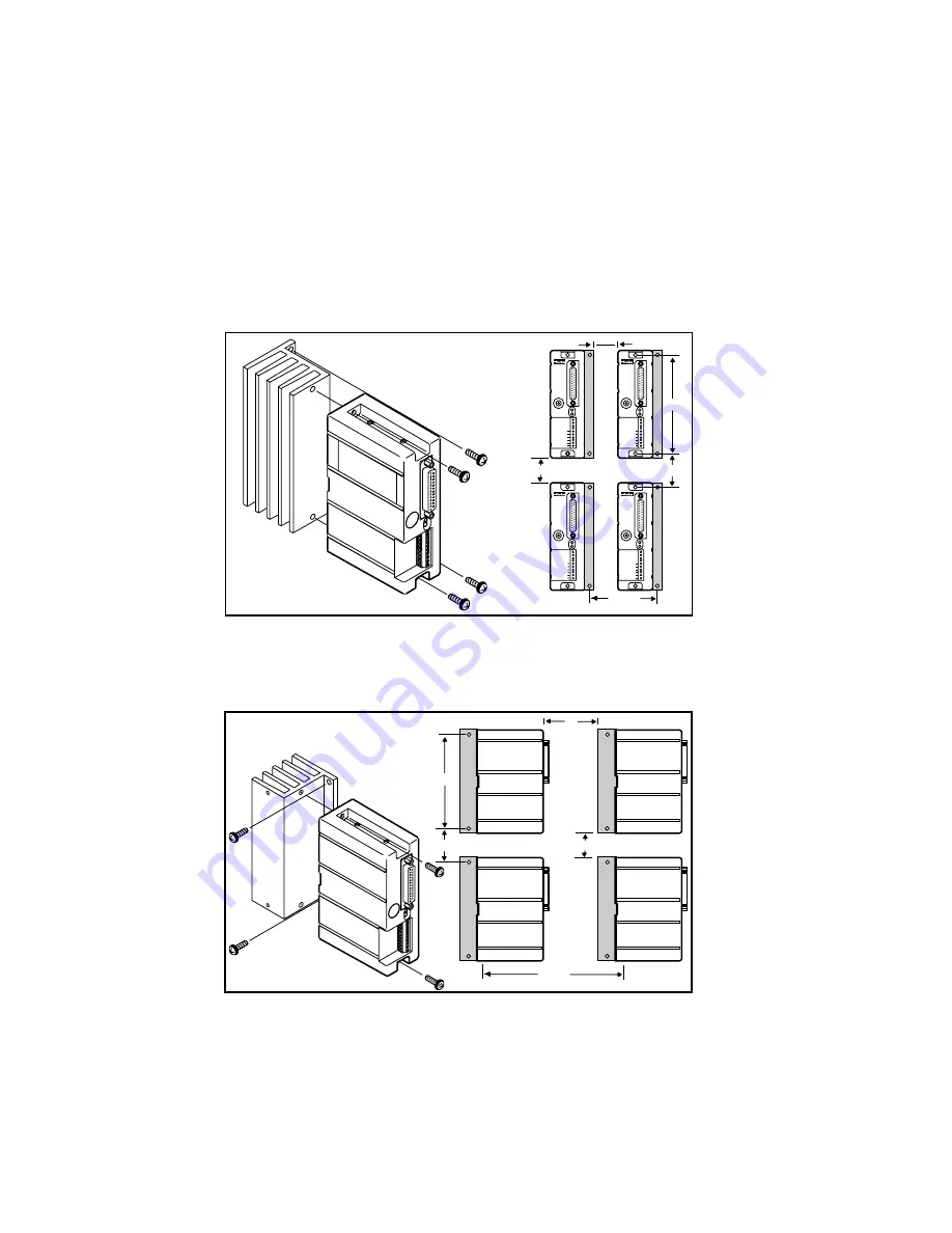
With the OEM-HS1, the drive may be mounted in two different
configurations (refer to Figures 2-14 and 2-15). One configuration
provides the maximum amount of panel or mounting space (mini-
mum area). The other configuration provides minimum depth.
Panel layout for minimum area is shown in Figure 2-14.
OEM
s
e
r
i
e
s
REMOTE
REF
CURRENT
DUMP
VDC+
VDC-
A+
A-
B+
B-
POWER
FAULT
OEM
s
e
r
i
e
s
REMOTE
REF
CURRENT
DUMP
VDC+
VDC-
A+
A-
B+
B-
POWER
FAULT
OEM
s
e
r
i
e
s
REMOTE
REF
CURRENT
DUMP
VDC+
VDC-
A+
A-
B+
B-
POWER
FAULT
OEM
s
e
r
i
e
s
REMOTE
REF
CURRENT
DUMP
VDC+
VDC-
A+
A-
B+
B-
POWER
FAULT
0 . 5 "
4 . 6 5 "
2 . 3 5 "
2 "
2 . 5 "
M i n i m u m
Figure 2-14. OEM650/OEM650X OEM-HS1 Minimum Area Panel Layout
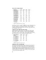
Panel layout for minimum depth is shown in Figure 2-15.
6 . 3 2 "
M i n i m u m B e t w e n M o u n t i n g H o l e s
2 . 3 5 "
4 . 6 5 "
3 "
2 "
Figure 2-15. OEM650/OEM650X OEM-HS1 Minimum Depth Panel Layout

