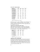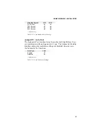
INSTALLATION • OEM650/OEM650X
22
Motor Mounting
Rotary stepper motors should be mounted with flange bolts and
positioned with the centering flange on the front face. Foot-mount or
cradle configurations are not recommended because the motor's
torque is not evenly distributed around the motor case and they offer
poor registration. Any radial load on the motor shaft is multiplied by
a much longer lever arm when a foot mount is used rather than a
face flange.
WARNING
Improper mounting can reduce system performance & jeopardize personal safety.
The motors used with the OEM650/OEM650X can produce very
large torques. These motors can also produce high accelerations.
This combination can shear shafts and mounting hardware if the
mounting is not adequate. High accelerations can produce shocks
and vibrations that require much heavier hardware than would be
expected for static loads of the same magnitude. The motor, under
certain profiles, can produce low-frequency vibrations in the mount-
ing structure. These vibrations can cause metal fatigue in structural
members if harmonic resonances are induced by the move profiles
you are using. A mechanical engineer should check the machine
design to ensure that the mounting structure is adequate.
CAUTION
Consult a Compumotor Applications Engineer [800-358-9070] before you machine the
motor shaft. Improper shaft machining can destroy the motor’s bearings.
Never
disassemble the motor (it will cause a significant loss of torque).
Attaching the Load
This section discusses the main factors involved when attaching the
load to the motor. The following three types of misalignments can
exist in any combination.
Parallel Misalignment
The offset of two mating shaft center lines, although the center lines
remain parallel to each other.
Angular Misalignment
When two shaft center lines intersect at an angle other than zero
degrees.
End Float
A change in the relative distance between the ends of two shafts.

