27
OEM650/OEM650X • INSTALLATION
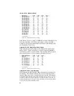
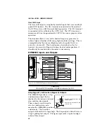
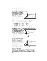
CW (Signal 3) & CCW (Signal 4) Limit Inputs
The OEM650X has two dedicated
hardware end-of-travel limits
(CCW and CW ). When you
power up the OEM650X, these
inputs are enabled (high). To test
the OEM650X without connect-
ing the CCW and CW limits, you
must disable the limits with the
LD3
command. You can use the
Limit Switch Status Report (
RA
) and Input Status (
IS
) commands to
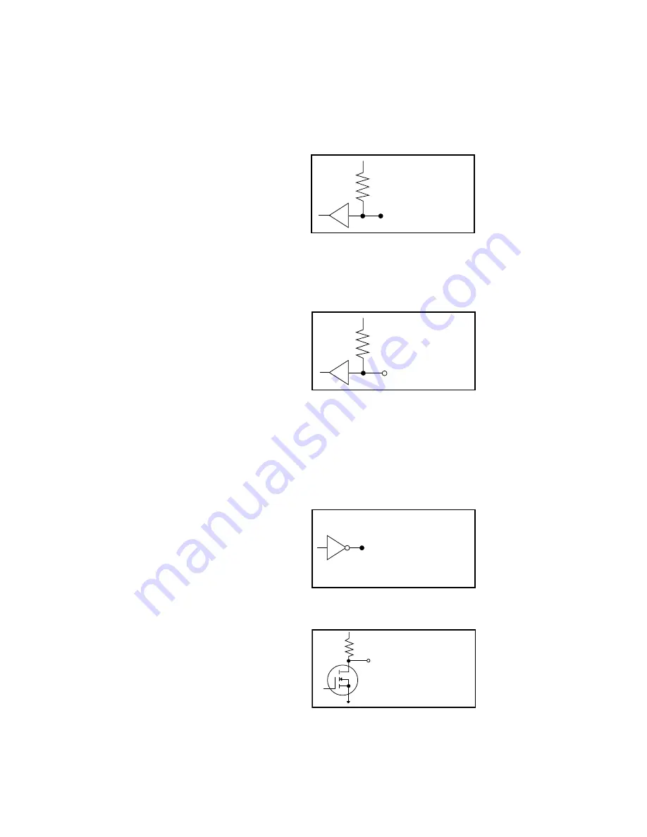
monitor the limits’ status. The figure represents a typical configura-
tion of these inputs.
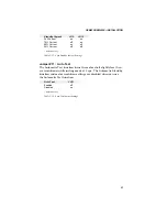
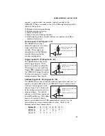
Home Position Input (Signal 5)
The OEM650X has one dedicated
home input. The Home Limit
input allows you to establish a
home reference input. This input
is not active during power-up.
Refer to the Go Home command
for more information on setting
up and using this function. The figure represents a typical configu-
ration of this input. (Refer to the
OS
and
GH
commands.)
Reserved (Signal 6)
This signal cannot currently be used to perform any function in this
release of the OEM650X. Additional functionality may be provided in
future revisions.
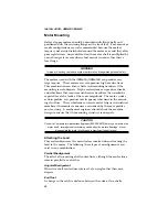
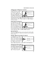
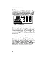
Output #1 (Signal 10) and Output #2 (Signal 8)
The OEM650X has two dedicated
programmable outputs. They
may be used to signal peripheral
devices upon the start or comple-
tion of a move. The default state
for Outputs #1 and #2 is logic
low. The figure represents a
typical configuration of these outputs. (Refer to the
O
command.)
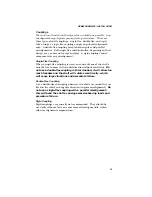
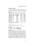
Dedicated Fault Output (Signal 9)
The OEM650X has one dedicated
fault output
.
This output may be
used to signal peripheral devices
if a unit failure occurs. The Fault
output's default state is logic
high. The figure represents a
• Maximum low-level input: 0.8V
(Sinks 1.2 mA)
• Minimum high-level input: 2V
+5V
4.75k
HCT541
BS170
+5V
+4.75k
• Maximum low-level output: 0.8V
(Sinks 1.2 mA)
• High-level output: 5V
• Minimum high-level output: 4.26V
(Source -24mA)
• Maximum low-level output: 0.44V
(Sinks @ 23 mA)
ACTØ4
• Maximum low-level input: 0.8V
(Sinks 1.2 mA)
• Minimum high-level input: 2V
+5V
4.75k
HCT244

