INSTALLATION • OEM650/OEM650X
30
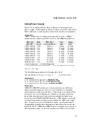
Daisy Chaining
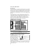
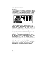
You may daisy chain up to 8 OEM650Xs. Individual drive addresses
are set with signals 23, 24, and 25 on the 25-pin D connector. When
daisy chained, the units may be addressed individually or simulta-
neously. You should establish a unique device address for each
OEM650X. Refer to Figure 2-20 for OEM650X daisy chain wiring.
OEM
s
e
r
i
e
s
REMOTE
REF
CURRENT
DUMP
VDC+
VDC-
A+
A-
B+
B-
POWER
FAULT
OEM
s
e
r
i
e
s
REMOTE
REF
CURRENT
DUMP
VDC+
VDC-
A+
A-
B+
B-
POWER
FAULT
OEM
s
e
r
i
e
s
REMOTE
REF
CURRENT
DUMP
VDC+
VDC-
A+
A-
B+
B-
POWER
FAULT
Rx
Tx
Gnd
Tx
Rx
Gnd
Tx
Rx
Gnd
Tx
Rx
Gnd
Figure 2-20. Daisy Chain Configuration
Commands prefixed with a device address control only the unit
specified. Commands without a device address control all units on
the daisy chain. The general rule is:
Any command that causes the
drive to transmit information from the RS-232C port (such as a status
or report command), must be prefixed with a device address
. This
prevents daisy chained units from all transmitting at the same time.
Attach device identifiers to the front of the command. The Go (
G
)
command instructs all units on the daisy chain to go, while
1G
tells
only unit #1 to go.
When you use a single communications port to control more than
one OEM650X, all units in a daisy chain receive and echo the same
commands. Each device executes these commands, unless this
command is preceded with an address that differs from the units on
the daisy chain. This becomes critical if you instruct any indexer to
transmit information. To prevent all of the units on the line from
responding to a command, you must precede the command with the
device address of the designated unit. No OEM650X executes a
device-specific command unless the unit number specified with the
command matches the OEM650's unit number. Device-specific
commands include both buffered and immediate commands.


