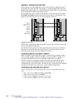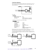
➁
Installation
11
Set it to control the drive’s motor pole compensation, based upon your motor’s electrical
time constant. The following table shows switch settings for Compumotor SM and
NeoMetric Series servo motors.
*Located on Bottom of Drive
off
off
off
on
off
off
off
on
off
on
on
off
off
off
on
on
off
on
off
on
on
on
on
on
MOTOR POLE COMPENSATION
1
2
3
off
1
2
3
SM161A, SM162A
Reserved
SM231A, B, B
Reserved
N0701D, N0701F
N0702E, N0702F
Reserved
N0703F, N0703G, N0704F,
N0704G, N0921F, N0921G, N0922G
TQ10 DIP SWITCH #3*
If you use a non-Compumotor motor, see the
Appendix
at the end of this User Guide for
information about setting DIP switches for your motor.
Offset Potentiometer—Do Not Adjust
Located next to DIP SW3 is a small potentiometer that controls the drive’s offset. It was
adjusted at the factory, and requires no further adjustment.
WARNING
Do not adjust the offset potentiometer. Lethal voltages are present inside the drive.
Adjusting the potentiometer with AC power applied can be hazardous to personnel.
Artisan Technology Group - Quality Instrumentation ... Guaranteed | (888) 88-SOURCE | www.artisantg.com


