Chapter 1. Installation
17
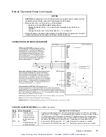
End-of-Travel and Home Limit Inputs
NOTES
• CAUTION
:
Use either the on-board
+5V
terminal or an external power supply to power
the
AUX-P
pull-up resistor (using both will damage the ZETA6xxx).
• Motion will not occur until you do one of the following:
- Install end-of-travel (
POS
&
NEG
) limit switches.
- Disable the limits with the
LHØ
command (recommended only if load is not
coupled).
- Change the active level of the limits with the
LHLVL
command.
• Refer to the Basic Operation Setup chapter in the 6000 Series Programmer’s Guide for
in-depth discussions about using end-of-travel limits and homing.
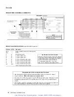
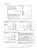
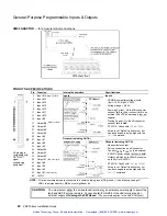
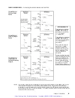
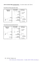
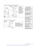
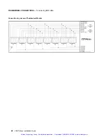
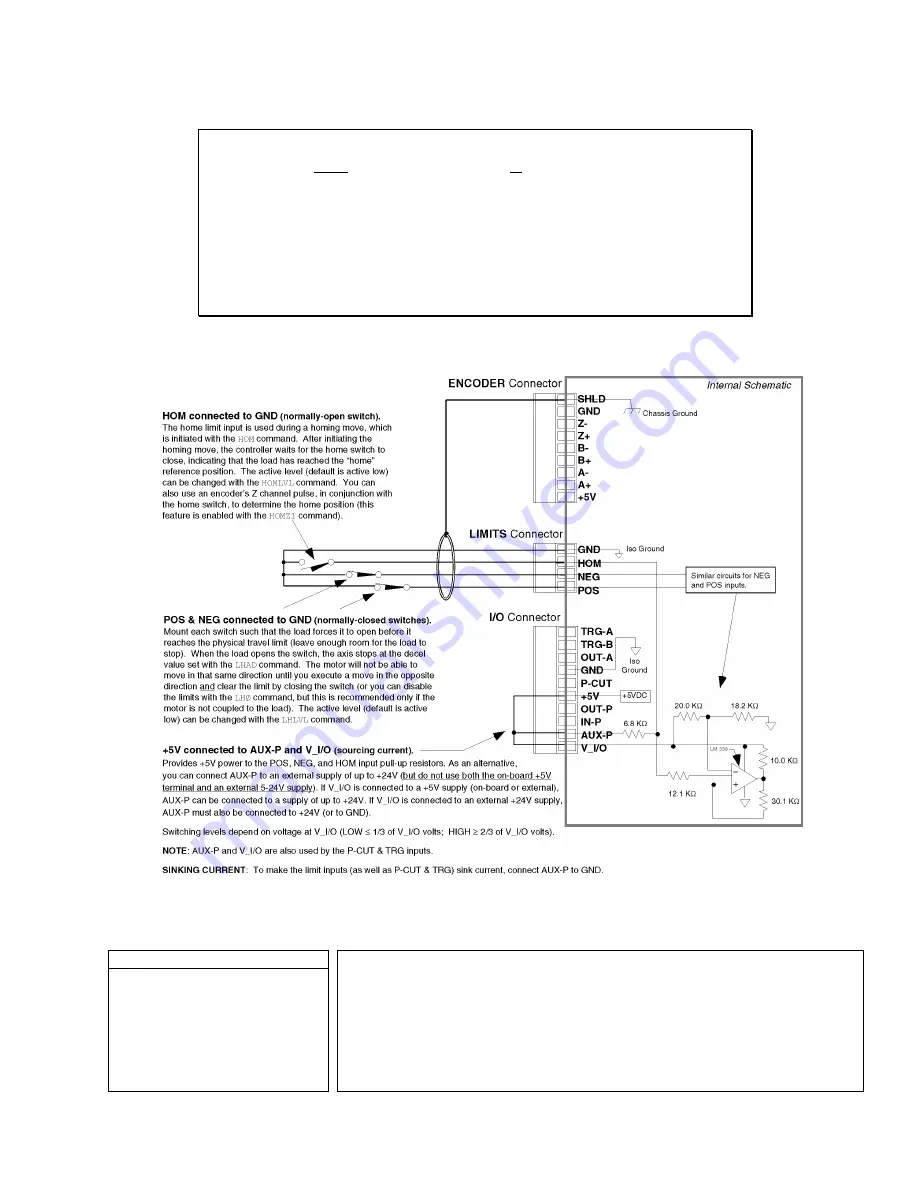
CONNECTIONS & INTERNAL SCHEMATICS
PIN OUTS & SPECIFICATIONS
(4-pin LIMITS Connector)
Name
In/Out
Description
Specification for all limit inputs
GND
HOM
NEG
POS
—
IN
IN
IN
Isolated ground.
Home limit input.
Negative-direction
end-of-travel limit
input.
Positive-direction end-
of-travel limit input.
• Powered by voltage applied to V_I/O terminal (switching levels: Low
≤
1/3 of V_I/O voltage,
High
≥
2/3 of V_I/O voltage). V_I/O can handle 5-24V with max. current of 100mA. Internal
6.8 K
Ω
pull-ups to AUX-P terminal—connect AUX-P to power source (+5V terminal or an
external 5-24V supply) to source current, or connect AUX-P to GND to sink current; AUX-P
can handle 0-24V with max. current of 50mA. Voltage range for these inputs is 0-24V.
• Active level for HOM is set with
HOMLVL
(default is active low, requires n.o. switch).
• Active level for POS & NEG is set with
LHLVL
(default is active low, requires n.c. switch).
Artisan Technology Group - Quality Instrumentation ... Guaranteed | (888) 88-SOURCE | www.artisantg.com


