Chapter 1. Installation
2 5
2.02
(51.31)
max.
Removable
insulating bushing
Construction = conduit. Connection
(1/2 NPS TAP) with 0.56 (14.22)
I.D. removable insulating bushing
R 1.72
(43.69)
0.06
(1.52)
0.18
(4.57)
1.25
(31.75)
-A-
0.002 (0.051)
¯0.3750
+
-
0.0000
0.0005
(9.53
+
-
0.000)
0.013)
L2
0.003 (0.077) -A-
Lmax.
0.344
(8.738)
1.25
(31.75)
0.75
(19.05)
full depth
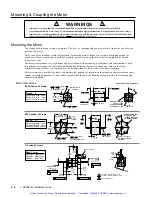
Flat Configuration = F
Standard Front Shaft Configurations
Double Shaft Configuration
1.25
(31.75)
0.50
0.02
+
-
(12.7
0.051)
+
-
0.374
+
-
0.000
0.010
(9.50
+
-
0.00)
0.26)
#303 Woodruff Key Configuration = W
0.0469
0.0050
+
-
(1.191
0.128)
+
-
0.002 (0.051)
¯0.3750
+
-
0.0000
0.0005
(9.53
+
-
0.000)
0.013)
1
Indicated dimension
applies from end of
extension to face of
rear end bell (cover
and gasket removed)
1.43
0.04
+
-
(36.32
1.02)
+
-
1
Model
Lmax
L2
RS31B- NPS
3.62
(n
n91.95)
2.87
(n
n72.90)
RS32B- NPS
4.77
(121.16)
4.02
(102.11)
RS32B- NPS
6.05
(153.67)
5.30
(134.62)
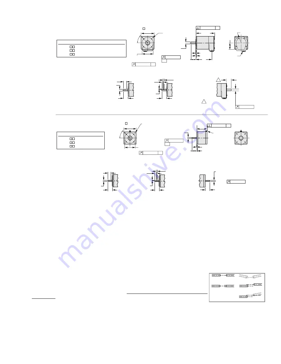
R Series, 23 Frame
End Bell Construction (NPS)
2 x 45
¡
4 x
¯0.218
(5.46) thru
equally spaced on a
¯3.875
(98.43) B.C.
0.003 (0.077) -A-
¯2.875
0.002
+
-
(73.025
0.051)
+
-
3.38
(85.85)
0.344
(8.738)
1.25
(31.75)
0.18
(4.57)
1.25
(31.75)
0.06
(1.52)
L max.
0.003 (0.077) -A-
¯.3750
+
-
0.0000
0.0005
(9.53
+
-
0.000)
0.013)
-A-
0.002 (0.051)
Motor leads (fly)
or with 10 ft
cable (R10)
0.75
(19.05)
full depth
Flat Configuration = F
Rear Shaft Configuration = D
¯0.3750
+
-
0.0000
0.0005
(9.53
+
-
0.000)
0.013)
0.002 (0.051)
1.12
0.04
+
-
(28.45
1.02)
+
-
Standard Front Shaft Configurations
Standard Double Shaft Configuration
Model
Lmax
RS31B- R10
2.58
(n
n65.54)
RS32B- R10
3.76
(n
n95.51)
RS32B- R10
5.06
(128.53)
R Series, 34 Frame
Regular Construction (R10)
2 x 45
¡
4 x
¯0.218
(5.46) thru
equally spaced on a
¯3.875
(98.43) B.C.
3.38
(85.85)
0.003 (0.077) -A-
¯2.875
0.002
+
-
(73.025
0.051)
+
-
1.25
(31.75)
0.0469
0.0050
+
-
(1.191
0.128)
+
-
0.50
0.02
+
-
(12.7
0.051)
+
-
0.374
+
-
0.000
0.010
(9.50
+
-
0.00)
0.26)
#303 Woodruff Key Configuration = W
Motor Temperature & Cooling
The motorÕs face flange is used not only for mounting; it is also a
heatsink
. Mount the face flange to a large thermal
mass, such as a thick steel plate. This is the best way to cool the motor. Heat will be conducted from inside the motor,
through the face flange, and dissipated in the thermal mass. You can also use a fan to blow air across the motor for
increased cooling, if you do not get enough cooling by conduction through the face flange.
In addition, the ZETA6104 has an automatic standby current feature that reduces motor current by 50% if no step
pulses have been commanded for a period of 1 second or more. (
WARNING
:Êtorque is also reduced.) Full current is
restored upon the first step pulse. To enable this feature use, the
DAUTOS1
command (default is disabled,
DAUTOS¯
).
The
DAUTOS
command setting is NOT automatically saved in non-volatile memory; therefore, if you intend to use this
mode on power up, you have to place the
DAUTOS1
command in a set-up (
STARTP
) programÑsee example on page 31.
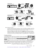
Coupling the Motor
To ensure maximum performance, align the motor shaft and load as accurately as possible (although
some misalignment may be unavoidable. The type of misalignment will affect your choice of coupler.
Single-Flex Coupling
: Use for angular misalignment only. One (only) one of the shafts must be
free to move in the radial direction without constraint. Do not use a single-flex coupling with parallel
misalignmentÑthis will bend the shafts, causing excessive bearing loads and premature failure.
Aligned
Parallel Misalignment
Combined Parallel & Angular Misalignment
End Float
Angular Misalignment
Double-Flex Coupling
: Use whenever two shafts are joined with parallel misalignment, or a combination of angular and
parallel misalignment. Single-flex and double-flex couplings may or may not accept end play, depending on their design.
Rigid Coupling
: Not recommended, because they cannot compensate for
any
misalignment. Use only if the motor or load is
on some form of floating mounts that allow for alignment compensation. Rigid couplings can also be used when the load is
supported entirely by the motorÕs bearings. A small mirror connected to a motor shaft is an example of such an application.
Coupling Manufacturers
:
HUCO, 70 Mitchell Blvd, Suite 201, San Rafael, CA 94903, (415) 492-0278
ROCOM CORP., 5957 Engineer Drive, Huntington Beach, CA 92649, (714) 891-9922
Artisan Technology Group - Quality Instrumentation ... Guaranteed | (888) 88-SOURCE | www.artisantg.com
Summary of Contents for Compumotor ZETA6104
Page 45: ...Artisan Technology Group Quality Instrumentation Guaranteed 888 88 SOURCE www artisantg com...
Page 49: ...Artisan Technology Group Quality Instrumentation Guaranteed 888 88 SOURCE www artisantg com...
Page 53: ...Artisan Technology Group Quality Instrumentation Guaranteed 888 88 SOURCE www artisantg com...
Page 63: ...Artisan Technology Group Quality Instrumentation Guaranteed 888 88 SOURCE www artisantg com...

