5 0
z
ZETA6104 Installation Guide
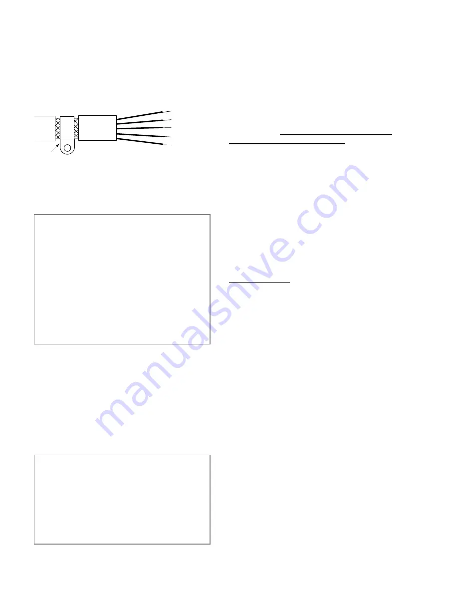
cable (this allows the braid to continue to the cable
connector), be careful not to damage the braid. Snap the
P-clip over the exposed braid, and adjust for a tight fit.
Secure the clip to the designated ground with a machine
screw and lock washer. The use of brass or other inert
conductive metal P-clip is recommended. Cover any
exposed bare metal with petroleum jelly to resist
corrosion.
P-Clip
Remove outer jacket only
do not cut braid
Figure 2. P-Clip Installation
Installation
External Enclosure
I n t r o d u c t i o n
The measures described in this section are primarily for the
purpose of controlling conducted emissions. To control
radiated emissions, all drive and control systems must be
installed in a steel equipment cabinet which will give
adequate screening against radiated emissions. This
external enclosure is also required for safety reasons. There
must be no user access while the equipment is operating.
This is usually achieved by fitting an isolator switch to the
door assembly.
To achieve adequate screening of radiated emissions, all
panels of the enclosure must be bonded to a central earth
point. The enclosure may also contain other equipment and
the EMC requirements of these must be considered during
installation. Always ensure that drives and controllers are
mounted in such a way that there is adequate ventilation.
Preparing the ZETA6104: The ZETA6104 must be
mounted to a conductive panel. Before mounting the
ZETA6104, remove the paint from the rear face of the
mounting hole that will be closest to the input filter
location as shown in Figure 3 below, and if necessary
from the corresponding area on the rear panel of the
enclosure. This is to guarantee a good high-frequency
connection between the drive case and the cabinet. After
mounting the unit use petroleum jelly on the exposed
metal to minimize the risk of future corrosion.
Filtering the AC Supply
I n t r o d u c t i o n
These recommendations are based on the use of proprietary
screen filter units which are readily available. However, the
full EMC test includes a simulated lightning strike which
will damage the filter unless adequate surge suppression
devices are fitted. These are not normally incorporated into
commercial filters since the lightning strike test can be
destructive. This test is normally carried out on the overall
system and not on individual components; therefore, the
surge protection should be provided at the system
boundary.
A filter must be installed between the incoming AC
supply and the input to the drive. The manufacturerÕs part
numbers for suitable filters are:
Corcom 10VV1
Corcom World Headquarters
Phone: 847-680-7400
Fax: 847-680-8169
Schaffner FN670-10/06
Schaffner EMC Inc.
Phone: 201-379-7778
Fax: 201-379-1151
Mount the filter within 2 inches (50mm) of the
ZETA6104 as shown in Figure 3 below. Ensure that there
is no paint on the mounting panel under the filter
mounting lugsÑit is vital that there is good large-area
contact between the filter and the panel.
Connect the incoming AC supply cable to the push-on
terminals on the filter, with the earth lead connected to a
local earth stud, bus bar or metal back-plane. Route the
supply cable so that it runs close to the walls of the
enclosure. Connect the earth terminal on the filter case to
the earth stud.
Fit a ferrite absorber over the cable before wiring the filter
output terminals to the AC input on the drive. Locate the
absorber as close as possible to the drive using heat-shrink
sleeving (see Figure 1 above). Take the ZETA6104 earth
connection from the same stud that retains the filter case
earth, as shown in Figure 3 below.
Motor Connections
Compumotor Motors
Parker Compumotor ZETA Series step motor systems
ship with motors that do not incorporate the use of a
braided screen for the control of conducted emissions.
Therefore, when used in installations where the motor
cable is not within earthed conduit the entire length of
travel, the standard motor cable should not be used.
At the drive end of the motor cable, fit a ferrite absorber
over the cable before wiring to the motor connector (it
may be necessary to remove the existing connector).
Locate the absorber as close as possible to the connector
using heat-shrink sleeving.
For motors with exposed cabling (not within earthed
conduit), follow the guidelines below:
¥ Removable Cabling: Remove the motor cable from
the standard motor, and replace with a suitable cable
described below, see
Motor Cables.
¥ Permanent Cabling: Cut off cable in excess of
approximately 4 inches (10 cm). Configure the motor
for series or parallel operation and attach a suitable
braided screen cable to the motor, see
Motor Cables
below.
Termination of the braid shield at the motor must be made
using a 360
°
bond to the motor body, and this may be
achieved by using a suitable clamp. Many stepper motors
are designed to accommodate an appropriate terminal gland
which can be used for this purpose. If this is not the case,
P-clip the braid to the rear end bell of the motor housing,
as shown in Figure 4. This will not only provide a good
high-frequency bond, but strain relief as well.
Artisan Technology Group - Quality Instrumentation ... Guaranteed | (888) 88-SOURCE | www.artisantg.com
Summary of Contents for Compumotor ZETA6104
Page 45: ...Artisan Technology Group Quality Instrumentation Guaranteed 888 88 SOURCE www artisantg com...
Page 49: ...Artisan Technology Group Quality Instrumentation Guaranteed 888 88 SOURCE www artisantg com...
Page 53: ...Artisan Technology Group Quality Instrumentation Guaranteed 888 88 SOURCE www artisantg com...
Page 63: ...Artisan Technology Group Quality Instrumentation Guaranteed 888 88 SOURCE www artisantg com...

