background image

Drive Controlled Pump

Parker Hannifin Corporation

Hydraulics Group

DCP Manual innen A4 UK.indd  06.11.17

7

Manual

Introduction

Initial steps

Use the manual to help you plan the following:

Installation

Know your requirements:
•  certification requirements, CE/UL/CUL conformance
•  conformance with local installation requirements
•  supply and cabling requirements

Programming (Parker Drive Quicktool) – pc pro-
gramming tool

Know your application:
•  Install the Parker Drive Quicktool (PDQ) after down-

loading it from www.parker.com/ssd/pdq

•  Connect your pc to your Drive via Ethernet
•  Commission your Drive with the Parker Drive Quick-

tool wizard

•  Go to Appendix D Parameter Reference for more in-

formation

PC REQUIREMENTS

Minimum system requirements:
•  1GB RAM
•  1GHz Pentium
•  1GB free Hard Disk space
•  1024x768 screen resolution

Operating Systems:

•  Windows XP
•  Windows Vista (32 bit)
•  Windows 7 (32 & 64 bit)
•  Windows 8 (32 & 64 bit)

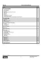
Summary of Contents for DCP3

Page 1: ...Drive Controlled Pump Installation Manual DCP3 ...

Page 2: ...sponsible for making the final selection of the system and components and assuring that all performance endurance maintenance safety and warning requirements of the application are met The user must analyze all aspects of the application follow applicable industry standards and follow the information concerning the product in the current product catalog and in any other materials provided from Par...

Page 3: ... for Control Main Cable 10 10 10 11 12 13 14 Installation Wiring instructions Power connections 15 15 15 Control wiring connections Inputs Analogue DCP3xxxA Inputs Fieldbus DCP3xxxC D E P N Control word 2021 Outputs Analogue DCP3xxxA Status word 2022 17 18 18 18 19 19 Option Modules Analogue Inputs Encoder and Motor Thermisor 20 21 21 Ethernet Introduction Status monitoring Setting the IP Address ...

Page 4: ...phical Keypad Fitting a remote GKP The Display Keys Soft key action indication Menu Organisation 32 32 33 33 34 35 Parker Drive Quicktool PDQ PC Software Installation Starting the wizard Task selection 37 37 38 38 Parameter description 44 Parameter list 51 Trips and Fault Finding 54 Technical data Environmental details Earthing Safety Details Electrical Ratings 400 V build variant Input fuse ratin...

Page 5: ...his equipment can endanger life by exposure to ro tating machinery and high voltages 2 The equipment must be permanently earthed due to the high earth leakage current and the drive mo tor must be connected to an appropriate safety earth 3 Ensure all incoming supplies are isolated before working on the equipment Be aware that there may be more than one supply connection to the drive 4 There may sti...

Page 6: ...mentary mitiga tion measures may be required This equipment contains electrostatic discharge ESD sensitive parts Observe static control precautions when handling installing and servicing this product This is a product of the restricted sales distribution class according to IEC 61800 3 It is designated as professional equipment as defined in EN61000 3 2 Permission of the supply authority shall be o...

Page 7: ...rements Programming Parker Drive Quicktool pc pro gramming tool Know your application Install the Parker Drive Quicktool PDQ after down loading it from www parker com ssd pdq Connect your pc to your Drive via Ethernet Commission your Drive with the Parker Drive Quick tool wizard Go to Appendix D Parameter Reference for more in formation PC REQUIREMENTS Minimum system requirements 1GB RAM 1GHz Pent...

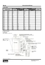
Page 8: ... D DCP3 7P5 3 7 5 2 2 5 5 D DCP3 010 4 10 3 7 5 D DCP3 012 5 5 12 4 10 D DCP3 016 7 5 16 5 5 12 E DCP3 023 11 23 7 5 16 E DCP3 032 15 32 11 23 F DCP3 038 18 38 15 32 F DCP3 045 22 45 18 38 G DCP3 060 30 60 22 45 G DCP3 073 37 73 30 60 G DCP3 087 45 87 37 73 H DCP3 105 55 105 45 87 H DCP3 145 75 145 55 105 H DCP3 180 90 180 75 145 J DCP3 205 110 205 90 180 J DCP3 260 132 260 110 205 J DCP3 380 200 ...

Page 9: ...es Models Max Weight H H1 H2 W W1 W2 D Fixings Size D 4 5 kg 286 270 6 5 100 80 10 255 4 5 mm slots holes M4 fixings Size E 6 8 kg 333 320 6 5 125 100 12 5 255 Size F 10 kg 383 370 6 5 150 125 12 5 255 Size G 22 3 kg 480 465 7 25 220 190 13 287 5 5 mm slots holes M5 fixings Size H 42 8 kg 670 650 10 260 220 20 316 6 8 mm slots holes M6 fixings Size J 89 kg 800 780 10 260 285 23 374 9 0 mm slots ho...

Page 10: ... pending on required level of EMC compliance refer to Ap pendix C Compliance Note Frame H J K only These models are heavy and will require two people to lift or the use of a fork lift to install it The product will stand vertically on flat surfaces Ventilation The drive gives off heat in normal operation and must therefore be mounted to allow the free flow of air through the ventilation slots and ...

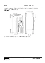
Page 11: ...ixing holes Note Frame H J and K have a single mounting plate which cannot be moved Mounting brackets frames D E F G The brackets can be moved up down by using the alternative holes which are set at 15 mm intervals Rear view showing fixing holes for cubicle mount Cubicle mounting details all frame size Series AC30V ...

Page 12: ...outside the cubicle Dimensions for through panel installation sizes D E F G H and J All dimensions are in millimetres Model H H1 H2 W W1 W2 D D1 Fixings Size D 250 262 6 79 1 5 82 72 181 Use M4 fixings Size E 297 309 6 102 1 104 72 181 Size F 347 359 6 127 1 129 72 181 Size G 440 455 8 7 9 195 0 4 195 8 95 190 Use M5 fixings Size H 617 641 12 218 4 5 227 99 211 Use M6 fixings Size J 745 765 10 275...

Page 13: ...the slot slightly push to the left to release the catch Frames E F G H and J Top Cover To remove insert a screwdriver into the slot and move to the right to release the catch and then slide off cover Bottom Cover To remove bottom cover insert a screwdriver into the slot and move to the left to release the catch and then slide off cover 5 Fit gasket to the drive so that an air tight seal will be ma...

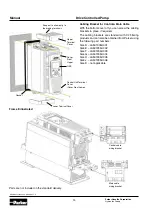
Page 14: ...rackets are standard with C2 filtering products and can also be obtained from Parker using the following part numbers Size D LA501935U001 Size E LA501935U002 Size F LA501935U003 Size G LA501935U004 Size H LA501935U005 Size J LA501935U006 Size K not applicable Main cable wiring bracket Parts are not included in the standard delivery Snap out to allow entry to the braking terminals Upper Terminal Co...

Page 15: ...CB GFCI are not recommended Installation Important The drive is only suitable for earth refer enced supplies TN when fitted with an internal fil ter External filters are available for use on TN and IT non earth referenced supplies For installations to EN 61800 5 1 in Europe For permanent earthing two individual incoming pro tective earth conductors 10 mm cross section or one conductor 10 mm cross ...

Page 16: ...he con trol module cover as follows 1 First remove the GKP by pulling from the top down and remove 2 Undo the screw and slide the control module cover down slightly then remove Control Module Removal Isolate supply before plugging or unplugging control unit to the power stack 1 Unscrew captive screw 2 Lift lower edge of assembly 3 Slide assembly upwards as far as possible to unlatch from unit ...

Page 17: ...astic collar Ferrule DIN462228 Pt4 maximum 0 75 mm2 Terminal ID Function X10 01 STO A Input X10 02 STO Common X10 03 STO B Input X10 04 STO Common X10 05 STO Status A X10 06 STO Status B X11 01 Anin 01 10V 0 10V 0 20mA 4 20mA X11 02 Anin 02 10V 0 10V X11 03 Anout 01 10V 0 10V X11 04 Anout 02 0 10V 0 20mA 4 20mA X11 05 10V reference X11 06 10V reference X12 01 Digin 04 Digout 01 X12 02 Digin 05 Dig...

Page 18: ... X13 04 Reset DIGIN04 X12 01 Pump 1 On Off Switch On Signal DIGIN05 X12 02 Pump 2 On Off Switch off Signal DIGIN06 X12 03 Terminal used as DIGOUT 03 DIGIN07 X12 04 Terminal used as DIGOUT 04 Selected Hydraulic Application Control Type Terminal Q Control p Control p Q Control LS Control Accumulator Control ANIN01 X11 01 Pressure Feedback 1 Pressure Feedback Pressure Feedback Pressure Feedback p0 Pr...

Page 19: ...ripped 2 Bypass Valve 1 3 Flow reached Pressure reached Flow reached Pressure reached reserved 4 reserved Pressure reached reserved 5 15 reserved Selected Hydraulic Application Control Type Terminal Q Control p Control p Q Control LS Control Accumulator Control ANOUT 01 X11 03 Actual motor speed ANOUT 02 X11 04 Command signal for pressure relief valve RELAY 01 X14 01 X14 02 Drive running RELAY 02 ...

Page 20: ... Description 7004 01 00 General Purpose I O Option referred to as GPIO Digital Inputs or Outputs Analogue Inputs Motor Thermistor Input Volt free Relay Outputs Real Time Clock 7004 02 00 Motor Thermistor Input 7004 03 00 Motor Thermistor and Real Time Clock 7004 04 00 Pulse Encoder and Motor Thermisto Terminal Name Range Description X20 01 DIN11 DOUT11 0 to 24 VDC Digital Input Output 11 See the n...

Page 21: ... the user 0 V sig nal reference with should be grounded at an appropriate point in the system If any analogue input are unused they should be con nected to X21 01 to prevent invalid values being reported Example Motor Thermistor Motor Thermistor Terminal Name Range Description X22 01 TH1 0 to 4 5 kΩ Connect motor thermistor between these two terminals X22 02 TH2 Terminal Name Range Description X22...

Page 22: ... the encoder inputs on X24 ter minals 01 to 04 Terminal Name Range Description X24 01 Channel A 3 V to 24 V differential or 0 V to 24 V Single Ended Encoder inputs compatible with a wide range of encoders X24 02 Channel A X24 03 Channel B X24 04 Channel B X24 05 Supply positive Selectable 5 V 12 V 15 V and 24 V Software selectable power supply output to encoder X24 06 Supply negative X24 07 Cable ...

Page 23: ...ia an Ethernet switch Status monitoring The MAC address of the Ethernet port is fixed at the fac tory and can be read using the parameter 0945 MAC Address The current IP settings of the AC30 can be monitored us ing the following parameters 0926 IP Address 0927 Subnet Mask 0928 Gateway Address The state of the Ethernet can be monitored using the pa rameter 0919 Ethernet State and from the Ethernet ...

Page 24: ...the AC30 each time the drive is powered up or when the Ethernet cable is plugged in There is no guarantee that the DHCP server will provide the same IP address each time The AC30 may assign itself a link local address automatically using Auto IP This would be used where an automat ic address is required but where no DHCP server is available such as a small local network or when connecting an AC30 ...

Page 25: ...ydraulics Group DCP Manual innen A4 UK indd 06 11 17 25 Manual Profibus communication with Siemens S7 Cyclic communication Acyclic communication Copy SFB52 to write and SFB53 to read from the internal library Define DBs as instances from SFB52 and SFB53 ...

Page 26: ...ulics Group DCP Manual innen A4 UK indd 06 11 17 26 Manual Acyclic communication ID is the Anybus diagnosis ID Click on the DP master system 1 Reading diagnostic ID 2 INDEX is always 255 LEN contains the size of record 3 RECORD should be set as shown 1 2 3 ...

Page 27: ...ifin Corporation Hydraulics Group DCP Manual innen A4 UK indd 06 11 17 27 Manual Acyclic communication 1 2 Parameter number is written to MB34 and MB35 1 Here 1928 INT 788 hex Value is written to MB36 MB39 2 Here 31 5 IEEE754 41FC hex ...

Page 28: ...0V STO function is a factory fitted and factory tested feature STO is a means of preventing an AC30V drive from de livering rotational force to its connected electric motor Please refer to EN61800 5 2 2007 para 4 2 2 2 for the formal definition To ensure a high degree of safety two independent STO control channels are implemented in hardware The STO circuit in the AC30V is designed such that a fau...

Page 29: ... to closed relay contacts when the STO circuit is in the safe state i e the drive will not cause its motor to produce torque However this output should be used pri marily as an indication In the unlikely event of a fault in the STO circuit this output could turn on erroneously to give a false indication of the STO status It must not be used as a gu arantee that the motor will not produce torque Th...

Page 30: ...e earthed otherwise it is possible to create an earth loop Applications Description The Drive Controlled Pump Applications provides 5 pump control configurations Q Control P Control p Q Control flow control with pressure control LS control Load sensing Accumulator Control Features Graphical user interface for hydraulic functions Supports variable and fixed displacement pumps Drive parameter settin...

Page 31: ... Speed Actual pressure DIGIN01 X13 02 DIGIN02 X13 03 DIGIN03 X13 04 DIGIN04 X12 01 DIGIN05 X12 02 RELAY01 X14 01 X14 02 RELAY02 X14 03 X14 04 DIGOUT 03 X12 03 DIGOUT 04 X12 04 Start No Stop Reset Pump1 On Off Pump2 On Off Drive running Not Tripped Bypass Valve Flow reached Pressure Setpoint ANOUT02 X11 04 CMD pressure valve amax nmin max Filter PWM P I Filter ANOUT01 X11 03 D Volume flow control Q...

Page 32: ...lank cover or if supplied separately to be used re motely up to 3 meters away use the mounting kit with connection lead Cut out details GKP Reverse side The yellow dotted line is the cutout detail to allow remote fitting the connection lead also shows screw hole details Use M3 x 10 self tapping screws Connection lead RS232 REM OPSTA with a Steward 28A2025 OAO connector All measurements in millimet...

Page 33: ...Only operates when Local start stop control mode is active Control Runs the motor STOP Control Stops the motor when local start stop control mode is active Trip reset Resets any trips Softkey 1 Navigation Displays the previous level s menu Edit Aborts the edit leaving the value unchanged Softkey 2 Changes the Local Remote Mode selection OK Navigation Displays the next menu level or parameter Chang...

Page 34: ...n shown above the key Return Abort Toggle between Local and Remote modes Soft Key 1 Softkey 1 is used as return or abort Soft Key 2 2 softkey is used to select the mode for the start stop control When navigating around the menu tree the return func tion navigates to the previous level In this case the re turn is the opposite of the OK key When changing a parameter value the Abort key discards any ...

Page 35: ... Control Accumulator Control Application Application Application Application Application App Selection App Selection App Selection App Selection App Selection Setup Pump Setup Pump Setup Pump Setup Pump Setup Pump Q Control p Control Q Control LS Control Accu Control Bypass valve Bypass valve p Control Bypass valve Bypass valve Analog Inputs Pressure valve Bypass valve Pressure valve Analog Inputs...

Page 36: ...ected Appli cation 1900 Selected Appli cation 1900 Selected Application 1900 Selected Appli cation 1900 Selected Applica tion 1901 Pump Type 1901 Pump Type 1901 Pump Type 1901 Pump Type 1901 Pump Type 1904 Double Pump 1904 Double Pump 1904 Double Pump 1904 Double Pump 1904 Double Pump 1905 Displacement Pump1 1905 Displacement Pump1 1905 Displacement Pump1 1905 Displacement Pump1 1905 Displacement ...

Page 37: ...71 Controller Output 1971 Controller Output 1968 Pressure Controller Kp 1968 Pressure Controller Kp 1968 Pressure Controller Kp 1969 Pressure Controller Ki 1969 Pressure Controller Ki 1969 Pressure Controller Ki 1970 Pressure Controller Kd 1970 Pressure Controller Kd 1970 Pressure Controller Kd 1973 Inner window Ipart 1973 Inner window Ipart 1973 Inner window Ipart 1974 Outer window Ipart 1974 Out...

Page 38: ...on Hydraulics Group DCP Manual innen A4 UK indd 06 11 17 38 Manual Once the InstallShield completes run the PDQ from the Start menu as shown or from the desktop shortcut Requires an Ethernet connection PC to Drive Task selection Starting the wizard ...

Page 39: ...will not respond to you Once the Drive detection is complete find your Drive in the list and click on it with the mouse Information about the se lected Drive will be displayed in the status area at the bot tom of the screen Ensure you have selected the correct Drive before continuing If Drive Brake Switch is not fitted it will be indicted by the symbol as shown in Figure 9 5 Note The selected driv...

Page 40: ...Drive Controlled Pump Parker Hannifin Corporation Hydraulics Group DCP Manual innen A4 UK indd 06 11 17 40 Manual Open DCP application Select application ...

Page 41: ...aulics Group DCP Manual innen A4 UK indd 06 11 17 41 Manual Setup DCP application Setup motor drive control IOs and communication Parameter can be set by clicking the appropriate icon Set customer specific motor data control strategy I Os and communication ...

Page 42: ...ion Hydraulics Group DCP Manual innen A4 UK indd 06 11 17 42 Manual Commission the drive Monitor and optimize the drive At this step the settings are whrite to the drive A drive name can be set to At parameter the optimization parameters can be set ...

Page 43: ...P Manual innen A4 UK indd 06 11 17 43 Manual Monitor and optimize the drive Monitor and optimize the drive Under application can view the history and state of active application Under scope can viewed and stored the profile of parameters Export as excel file is possible ...

Page 44: ...t to default DCPxxxxxxxxxxxA0000 If the pump is not configured via the DCP code this param eter sets the max speed of the drive If a double pump is se lected the lower max speed of both pumps has to be se lected entered The DCP code has to be set to default DCPxxxxxxxxxxxA0000 If the pump is not configured via the DCP code this param eter sets the max pressure of pump 1 If a double pump is install...

Page 45: ... name Pressure Setpoint Pressure Setpoint Fieldbus Actual pressure p0 Pressure window Parameter description Pressure setpoint bar Pressure setpoint of pump given by fieldbus bar Actual pressure p0 bar Window for Pressure reached bar Function This value displays the target pressure The value results from the input signal at ANIN02 p LS control ANIN11 pQ control or the communication interface field ...

Page 46: ...cumulator charging cycles can be defined individually When exceeding the max number of too short accumu lator charging cycles a warn ing message is generated The minimum time between two ac cumulator charging cycles can be defined individually When exceeding the max number of too short accumu lator charging cycles an error message is generated The minimum time between two ac cumulator charging cyc...

Page 47: ...gra tor stops working and the out put will stay constant This value limits the output of the integrator of the pressure controller in a positive direction Menu item Monitor Application Status p LS pQ Control Monitor Application Controller Status PNO 1976 1977 1978 1982 Parameter name Neg Limit Ki Rate Feedback Pressure Controller Td Controller yp Parameter description Negative limit of I part Spee...

Page 48: ...d if actual speed minimal speed hysterisis This parameter is set to TRUE if set DOUT03 for open by pass valve Menu item Setup Application Analog Inputs Monitor Application Digital IOs PNO 2000 2001 2002 2003 Parameter name Filter Analog Input01 Filter Analog Input02 Filter Analog Input11 Start Parameter description Filter of analog input 01 Filter of analog input 02 Filter of analog input 11 Start...

Page 49: ...testing Simulating of DIN03 Via this parameter the actual error of the drive can be resetted This parameter is only used for testing Simulating of DIN04 Via this parameter pump 1 can be turned on or off It can be used for a double pump only This parameter is only used for testing Settings Testfunction Menu item Monitor Application Testfunction PNO 2041 2042 2043 2044 Parameter name P1 Testmovement...

Page 50: ...is active Menu item Monitor Application HPU Messages PNO 2053 2054 2055 2056 Parameter name HPU Cont No warning HPU Cont No error HPU Oil No warning HPU Oil No error Parameter description No warning of filter is active No error of filter is active No warning oil level No error oil level Function This value is set toTRUE if the warning of the electrical dust indication of the filter is active This ...

Page 51: ... Control 1920 Flow window Setup Application Q Control REAL 0 0 to 1000 LPM ALWAYS Q pQ 1921 Flow window time Setup Application Q Control TIME 0 0 to 60 S ALWAYS Q pQ 1922 Qmax at 100 AIN02 Setup Application Analog Input Q REAL 0 0 to 1000 LPM ALWAYS Q pQ Setup Application Analog Input pQ 1923 Flow reached Monitor Application Digital IOs BOOL FALSE NEVER LS 1924 Leakage Comp Flow Favourites REAL 0 ...

Page 52: ...trol REAL 0 0 to 500 BAR NEVER LS 1962 Actual pressure LS Monitor Application Status LS Control REAL 0 0 to 500 BAR NEVER LS 1963 Max p Sensor LS Setup Application LS Control REAL 0 0 to 500 BAR ALWAYS LS 1968 Pressure Controller Kp Monitor Application p Control REAL 0 001 0 to 100 BAR ALWAYS p p Q LS Monitor Application p Q Control Monitor Application LS Control 1969 Pressure Controller Ki Monito...

Page 53: ... ALL 2004 No Stop Monitor Application Digital IOs BOOL FALSE NEVER ALL 2005 Reset Monitor Application Digital IOs BOOL FALSE NEVER ALL 2006 Pump 1 or Switch On Monitor Application Digital IOs BOOL FALSE NEVER ALL 2007 Pump 2 or switch Off Monitor Application Digital IOs BOOL FALSE NEVER ALL 2010 Drive Running Relay01 Monitor Application Digital IOs BOOL FALSE NEVER ALL 2011 No Drive Error Relay02 ...

Page 54: ...until the temperature is below the trip level You can reset the trip as follows 1 Press the STOP key to reset the trip and clear the alarm from the display 2 In remote terminal sequencing mode create a 0 to 1 transition on the RESET TRIP bit bit 7 in the App Control Word parameter 3 In remote communications sequencing mode create a 0 to 1 transition on the RESET TRIP bit bit 7 in the Comms Control...

Page 55: ...limit 200 seconds Motor loading too great FIXED BOOST level set too high 8 INVERSE TIME A prolonged overload condition exceeding the Inverse Time allowance has caused the trip Remove the overload condition 9 MOTOR I2T Only for PMAC Motor A prolonged load condition exceeding the motor rated current has caused the trip The estimated motor load has reached a value of 105 10 LOW SPEED I The motor is d...

Page 56: ...less Vector mode 27 STO ACTIVE Attempt to run the motor with the Safe Torque Off active Check the STO wiring It may be necessary to power the drive off and on to completely clear this event 28 FEEDBACK MISSING The drive has been configured to run in Closed Loop Vector control mode which requires a Pulse Encoder IO Option but the IO Option has not been correctly configured 29 INTERNAL FAN FAIL An i...

Page 57: ...educe the number of parameters being accessed by the fieldbus communications option 1007 Uninitialized pointer Record the error message and contact Technical Support 1010 Initialization error Record the error message and contact Technical Support 1101 to 1111 1200 to 1299 Communications option error Ensure the communications option is correctly fitted Update the firmware in the AC30 Replace the co...

Page 58: ...g Faulty cabling or connections wrong Faulty drive Check for problem and rectify before replacing with correct fuse Contact Parker Cannot obtain power on state Incorrect or no supply available Check supply details Motor will not run at switch on Motor jammed Stop the drive and clear the jam Safe Torque Off circuit active Check the STO connections then power the drive off and on to clear any latche...

Page 59: ...s 3C1 rural and 3C2 urban for all nine defined substances as defined in table 4 Classes 3C1 and 3C2 are valid for both storage and transportation purposes Note Product was tested and validated with a hydrogen sulphide environment of 25ppm for a conti nuous period of 1200 hours and validated throughout the test period without failure Vibration Test Fc of EN60068 2 6 10Hz f 57Hz sinusoidal 0 075mm a...

Page 60: ...roduct Code Motor Power Output Current A Input Current A Estimated Effici ency Switching Frequency kHz nominal maximum Output Current Derate kHz applied above nominal switching frequency Frame D Input currents for kW ratings are at 400V 50Hz ac input and for Hp ratings at 460V 60Hz ac input Prospective short circuit current 5kA Normal Duty Output Overload Motoring 110 for 60s DCP33P5 1 1 kW 3 5 4 ...

Page 61: ...d for Hp ratings at 460V 60Hz ac input Prospective short circuit current 5kA Normal Duty Output Overload Motoring 110 for 60s DCP3032 15 kW 32 28 5 97 4 12 6 3 20 PS 27 24 5 DCP3038 18 5 kW 38 33 5 97 4 12 6 7 25 PS 36 30 2 Heavy Duty Output Overload Motoring 150 for 60s 180 for 0 3s short term rating DCP3032 11 kW 23 21 7 97 4 12 6 0 15 PS 21 19 1 DCP3038 15 kW 32 28 5 97 4 12 6 1 20 PS 27 24 5 P...

Page 62: ...ut Overload Motoring 150 for 60s 180 for 3s short term rating DCP3087 37kW 73 66 98 3 08 7 7 50Hp 65 58 5 DCP3105 45kW 87 79 5 98 3 08 6 9 60Hp 77 70 DCP3145 55kW 105 97 4 98 3 08 8 6 75Hp 96 87 Power Supply 380 480 V 10 50 60 Hz 5 Motor power output current and input current must not be exceeded under steady state operating conditions Minimum repetitive power up power down cycle time 10 min Produ...

Page 63: ...ad Motoring 110 for 60s DCP315 160kW 250Hp 315 302 276 279 98 2 08 8 5 DCP380 200kW 300Hp 380 361 343 333 98 2 08 7 7 DCP440 250kW 350Hp 440 414 428 389 98 2 08 8 3 Heavy Duty Output Overload Motoring 150 for 60 s 18 0 for 3 s short term rating DCP315 132kW 200Hp 260 240 229 225 98 2 08 7 7 DCP380 160kW 250Hp 315 302 276 279 98 2 08 6 9 DCP440 200kW 300Hp 380 361 344 334 98 2 08 7 5 Input fuse rat...

Page 64: ... ke Dissipation kW hp Minimum Brake Resistor Value Ω 20 s maximum 30 duty 400V Build Variant 380 480V 10 50 60 Hz 5 DC link brake voltage 765 V DCP3032 15 20 21 5A 16 5 22 5 14 4 11 15 35 DCP3038 18 25 29 4A 22 5 30 19 6 15 20 26 Product Code Motor Power kW hp Brake Switch Peak Current A Peak Brake Dissipation kW PS Brake Switch Continuous Cur rent A Continuous Bra ke Dissipation kW hp Minimum Bra...

Page 65: ... 20 mA 4 to 20 mA Absolute maximum input current 25 mA in current mode AIN1 only Maximum rated output current in voltage mode 10 mA with short circuit protection Absolute maximum input voltage 24V dc in voltage mode Impedance Input impedance Load impedance Voltage range 22kW Voltage range 1kΩ Current range 120R Current range 600Ω Resolution 12 bits 1 in 4096 over full range 11 bits 1 in 2048 Accur...

Page 66: ... Pro tection Indefinite Digital outputs DIO1 X12 01 DIO4 X12 04 conforming to EN61131 2 Relays RL1 X14 01 X14 02 RL2 X14 03 X14 04 These are volt free relay contacts User 24 V supply output X13 05 Nominal Open Circuit Output Voltage 24V minimum 21V Rated Output Current 140mA The total current available is 140mA either individually or as the sum of all digital out puts and User 24V Supply Maximum V...

Page 67: ...ut at analogue input 02 Qmax Displacement ccm 100 Speed rpm 1000 If the target flow is sent via fieldbus this pa rameter is not required Step 4 Pmax at 100 AIN02 11 Maximum target pressure at 100 input at an alog input 02 Application p LS Control or an alog input 11 Application pQ Control If the target pressure is sent via fieldbus this parameter is not required Step 5 Upper Limit pressure Limits ...

Page 68: ...erload of the DC Link Voltage the choosen time should not be too short The result would be an error Motor name plate Base Frequency Rated Motor Current Motor poles Base voltage Nameplate speed Set of in and outputs In these settings it can be selected if the in and outputs are voltage or current signals In the Base IO the standard in and outputs are listed In the option file the expanding in and o...

Page 69: ...poration Hydraulics Group DCP Manual innen A4 UK indd 06 11 17 69 Manual Control Screen Check Target and Actual Values for Pressure and Flow Inputs and Outputs Check digital and analogue In Outputs Commissioning the drive Perform signal check ...

Page 70: ...Drive Controlled Pump Parker Hannifin Corporation Hydraulics Group DCP Manual innen A4 UK indd 06 11 17 70 Manual To optimize the drive please use the Quick Monitor Change parameter values ...

Page 71: ...asteurope parker com NL The Netherlands Oldenzaal Tel 31 0 541 585 000 parker nl parker com NO Norway Asker Tel 47 66 75 34 00 parker norway parker com PL Poland Warsaw Tel 48 0 22 573 24 00 parker poland parker com PT Portugal Tel 351 22 999 7360 parker portugal parker com RO Romania Bucharest Tel 40 21 252 1382 parker romania parker com RU Russia Moscow Tel 7 495 645 2156 parker russia parker co...

Reviews: