HY28-2668-01/GC/NA,EU
GOLD CUP
®
Series - Application Manual
Piston Pumps & Motors
3.2
Parker Hannifin Corporation
Hydraulic Pump Division
Marysville, Ohio USA
Section 3
The following sections detail the operation of the controls described above.
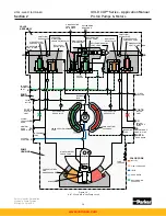
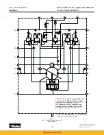
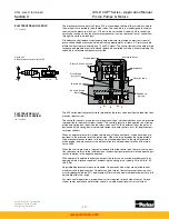
The internal configuration section of this manual describes in detail the hydraulic operation of
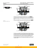
the rotary servo input control. Mechanically the rotary servo control is an arm and shaft as-
sembly carried in a bore in the control cover (see Figure 3.1).
Carried in the arm are a pair of shoes, one of which, (servo shoe) acts as a 4-way shear seal
valve in conjunction with the servo plate. The other, (balance shoe) bears against the control
cover and balances the force loads on the arm created by servo pressure acting on the servo
shoe. Both shoes are sealed with o-rings and are held against the control cover and servo
plate by a spring washer. A dowel pin is pressed into the arm and extends into a slot in the
control cover.
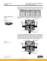
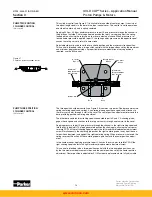
Servo pressure is fed into the control cover through a port in the pump case. It is carried
through a channel, around the rotary servo input shaft, then to a port through which the pres-
sure is fed to the servo shoes. Servo pressure feeds through the center of both shoes and
bears against the servo plate and control cover. Servo pressure is available to the shoes on
both the rotary servo input arm and the displacement indicator arm for balance and to allow
mounting the control input on either side of the pump.
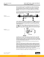
Servo pressure partially floats the servo shoes and reduces friction so the basic rotary servo
control without spring centering only requires 2 lbs-in. (0.23 Nm) torque to rotate. The servo
rotates through an arc of ±19° from zero to full displacement in both directions, and is de-
signed to accept the full error signal of 38° (pump at full displacement one direction, input full
displacement in the other direction). Motion of the input servo arm is stopped at full displace-
ment by roll pins pressed into the control cover. On the input side of the pump the rotary servo
shaft is left bare while a pointer is pressed onto the indicator shaft on the output side.
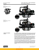
The pump is capable of having the rotary servo input on either side, but it is necessary to
change the control covers, servo stems, servo plate and the balance plate. These parts may
be transferred from side to side on the pump and do not need to be exchanged for other parts.
It may be necessary to disassemble and rearrange the contents of the control cover to allow it
to function correctly.
ROTARY SERVO INPUT
Figure 3.1
Control cover - rotary servo input
www.comoso.com


