HY28-2668-01/GC/NA,EU
GOLD CUP
®
Series - Application Manual
Piston Pumps & Motors
3.11
Parker Hannifin Corporation
Hydraulic Pump Division
Marysville, Ohio USA
Section 3
(800 and 900 series)
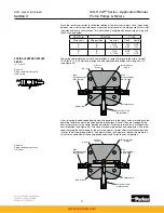
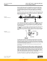
When both the input rotary servo control and the rocker cam are coincident in the neutral
position, (see Figure 3.15) the centering trimmer sleeve and mating spool are positioned
to bypass pilot flow to case, and a hole in the brake and bypass shoe is open to case. This
vents the pressure from the two cavities which are connected through small orifices to servo
pressure. These cavities are connected to the left of both pistons and the spring causes the
pistons to move to the left in the bore. This opens the brake port to case pressure and permits
the bypass valve spool to shift, connecting the pressure port to the replenishing port.
When both the input rotary servo control and the rocker cam are on stroke, (See figure 3.16)
the centering trimmer sleeve and mating spool are positioned to block pilot flow to case, and
the hole in the brake and bypass shoe is plugged off by the servo plate. This allows pressure
to build to servo pressure in the areas to the left of both pistons. This forces the pistons to the
right in their bore, opening the brake port to servo pressure and closing off the connection
between system pressure and replenishing ports.
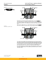
When the input rotary servo control is on stroke but the rocker cam is at zero stroke, (for ex-
ample, when the rotary servo is initially stroked off of neutral or the transmission is changing
direction of rotation), the hole in the brake and bypass shoe is open to case, but the centering
trimmer sleeve and mating spool are positioned to block pilot flow to case. This allows pres-
sure to build to servo pressure in the area to the left of piston -1. This forces both piston -1
and piston -2 to the right in the bore, opening the brake port to servo pressure and closing off
the connection between pressure and replenishing ports.
When the input rotary servo control is in the neutral position but the rocker cam is on stroke,
(for example, during dynamic braking), the centering trimmer sleeve and mating spool are
positioned to bypass pilot flow to case, however the hole in the brake and bypass shoe is
plugged off by the servo plate. This allows pressure to build to servo pressure in the area to
the left of piston -2. This forces piston -2 to the right in the bore, opening the brake port to
servo pressure and closing off the connection between pressure and replenishing ports.
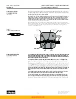
A feedback connection tee’d off the brake port, through an orifice to the end of piston -1 pro-
vides toggle action shifting.
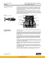
The brake and neutral bypass control has spring centering with a neutral adjustment. The
neutral adjustment can be adjusted for +/- 5% pump stroke. Adjustable maximum volume
displacement stops can be set anywhere from zero to 100% stroke.
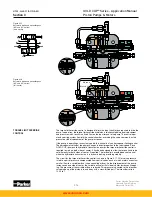
Figure 3.14
Automatic brake and neutral bypass
(400 and 500 series)
(input zero, output on stroke)
M a x . D
i s
p l .
A d j . S c r e w
R o t a r y S e r v o S h a f t
C o n t r o l
C o v e r
M a x . D
i s
p l .
A d j . S c r e w
N e u t r a l Tr
i
m .
A d j . S c r e w
P
i
n
L o n g P
i
n
To R e p l e n
i s
h m e n t
C u
s
t o m e r
S u p p l
i
e d
B r a k e
S e r v o
P l a t e
B y p a
s s
S h o e
B a l l
A d j u
s
t a b l e
P
i
n
S y
s
.
P r e
s s
.
P
i s
t o n - 1
P
i s
t o n - 2
L
i
g h t S p r
i
n g
H e a v y S p r
i
n g
P o r t Z
www.comoso.com


