background image

HY28-2668-01/GC/NA,EU

GOLD CUP

®

 Series - Application Manual

Piston Pumps & Motors

4.3

Parker Hannifin Corporation
Hydraulic Pump Division
Marysville, Ohio USA

Section 4

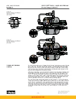
The circuit drawing (Figure 4.4) shows the directional control valves as closed center parallel 
valves. While these are the most desirable for this circuit, it is also possible to use parallel 
system, open center valves which are normally used with fixed displacement pumps. In this 
case, it is required to put some restriction or back pressure in the high pressure carry-over 
port in order to build the pressure drop in the neutral position above the minimum compensa-
tor setting of the pressure compensator override. With this back pressure added to the valves 
and when the valves are all in neutral position, the pump will be commanded to low pressure 
due to the absence of pressure in the load circuits, and will be held to minimum displacement. 
Without the back pressure, it is possible for the pump to be on stroke, although at low pres-
sure. 

In the closed center system shown, in the neutral position the pump will be at low pressure, 
again due to the lack of pressure in the load ports and will be at minimal flow due to the 
blocked center position of the valves. 

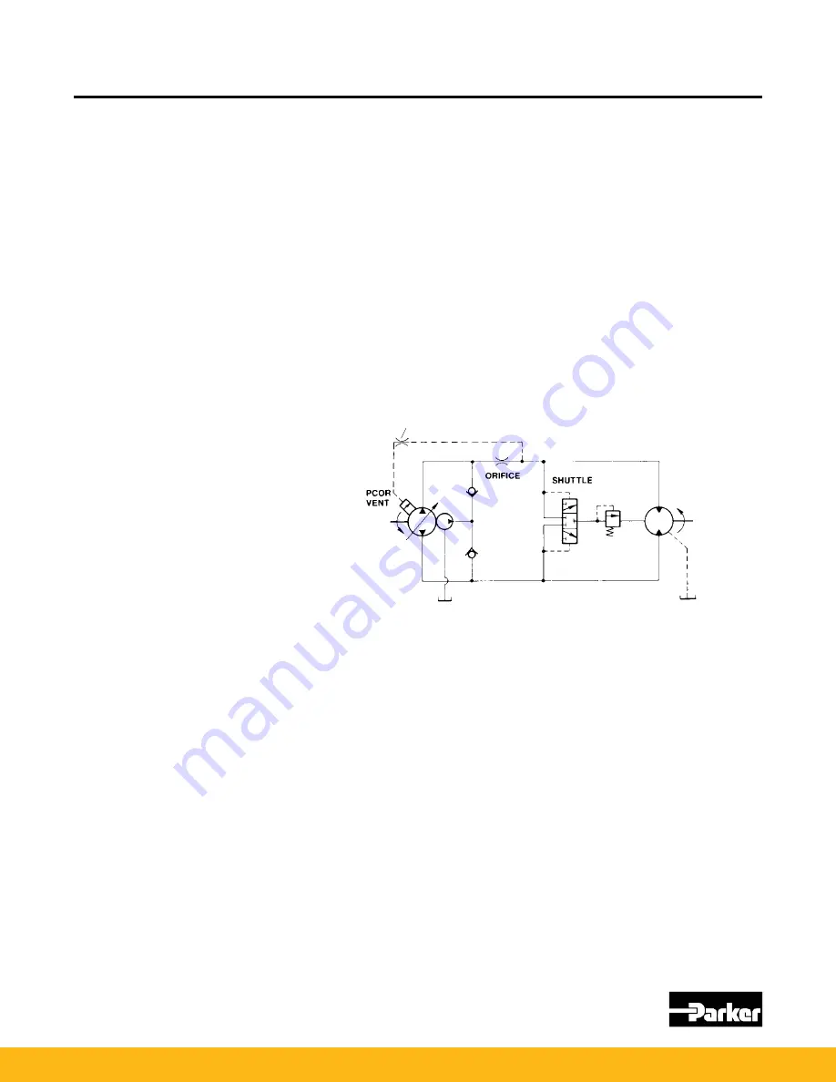
The enclosed circuit shows shuttle valves providing the load sensing logic to the vent port of 
the pressure compensator override. Valve suppliers may provide this logic in the secondaries 
of the control valve stacks. These valves may also contain the bleedout orifices as well.

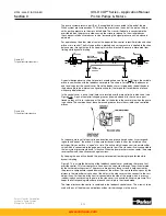
Some applications require constant controlled speeds from an actuator despite varying en-
gine speeds. These applications include transit mixers, generators and refrigeration systems. 
The GOLD CUP

®

 pumps can be readily adapted to this type of system by using the modified 

valve block with no orifice in the sequence poppet, with the addition of an orifice and a vent 
line as shown in the circuit in Figure 4.5.

In this circuit, the top of the compensator sequence valve (see Circuitry Section 2) is con-
nected to the load side of the orifice by the vent line. When the pressure drop through the 
orifice exceeds the pressure value of the spring on the sequence poppet the poppet rises and 
allows flow into the stroking chamber. This action is independent of system pressure as long 
as the pressure compensator override setting is not exceeded.

The above described system operates only in one direction of flow and only in the driving 
mode. It does not regulate speed in reverse or during overhauling loads. If speed control is 
desired in both directions, another orifice and vent line must be installed in the other system 
leg. If the system will reverse but regulation is not desired, a reverse flow check should be 
installed around the orifice. Even with additional vent lines and orifices in the opposite leg, 
regulation will occur only in the driving mode. If regulation is required while retarding, contact 
the Application Engineering Department.

On certain types of machines, it is desirable to have a control which will prevent motion of 
the machine without an operator at the controls. Venting the compensator when the opera-
tor is not at his station will remove power from the transmission. Pump venting when under 
pressure should be avoided. Consult Parker if necessary to vent under pressure (see Figure 
4.1). If the machine is not moving, it should remain stationary. If it is moving, it will coast until 
it stops. It should be noted that the machine will not stop rapidly with a vented compensator. If 
it is required to stop rapidly, or hold on a grade, the same sensor that vents the compensator 
should also set a parking brake.

Figure 4.5
Constant speed drive

CONSTANT SPEED DRIVES

DEAD MAN CONTROL

.047, 1mm ORIFICE

www.comoso.com

Summary of Contents for Denison GOLD CUP series

Page 1: ...mechanical filtration fluid gas handling hydraulics pneumatics process control sealing shielding DenisonGOLDCUP ApplicationHandbook PistonPumps Motors For Open Closed Circuits HY28 2668 01 GC NA EU Effective June 01 2013 www comoso com ...

Page 2: ...s warranty that the products would conform thereto We are selling the goods and merchandise illustrated and described on this publi cation on an as is basis and disclaim any implied warranty including any warranty of merchantability or warranty of fitness for any particular purpose whatsoever with respect to the goods and merchandise sold All manufacturer warranties shall be passed on to our custo...

Page 3: ...s to the position commanded by the rotary servo the vane ports which are connected to the cradle assembly provide the feedback to once again block the servo passages in and out of the vane chamber The pressure balance of the rotary servo stem insures that only minimal torque is required for the input signal The close tolerance between the vane chamber ports and the servo stem insures that any erro...

Page 4: ... servo input 3 2 Spring centering rotary servo 3 3 Figure 3 2 Spring centered rotary servo zero stroke 3 3 Figure 3 3 Spring centered rotary servo on stroke 3 3 Adjustable stops 3 4 Manual screw adjustment 3 4 Figure 3 4 Manual screw adjustment 3 4 Motor cylinder control 3 4 Figure 3 5 Motor cylinder control max stroke 3 5 Figure 3 6 Motor cylinder control min stroke 3 5 Pump two position cylinder...

Page 5: ... 4 7 Additional replenishment flow 4 5 Engine startup 4 5 Cold startup 4 5 New system or new component startup 4 6 System filtration 4 6 Cleaning procedures 4 7 Shaft type selection 4 7 Applying splined shafts 4 8 Applying keyed shafts 4 8 Series6 Variable volume pump with 1 07 in3 rev 17 5 cc rev aux pump 5 1 Series6 Variable volume motor 5 2 Series7 Variable volume pump with 1 07 in3 rev 17 5 cc r...

Page 6: ... piston variable volume pump consisting of a shaft driven cylinder barrel and pistons The barrel is made of steel with bronze liners in the cylinder bores It is supported by a large diameter roller bearing located in line with the radial forces generated by the pumping action Because of its location this bearing prevents the barrel from tipping at high speeds and high pressures and gives the pump ...

Page 7: ... the rocker cam are a pair of posts to hold the stroking vanes The vanes are held in slots in the posts and each consists of a Teflon seal held between two backup plates See figure 1 2 The seal is held outward against the walls of the stroking chamber by an o ring and servo pressure which is fed into the center of the Teflon seal through slots in the backup plates and a small shuttle valve Figure 1 3...

Page 8: ...p see Figure 1 5 The servo plate has two holes which connect directly to the channels in the servo stem while the balance plate is blank and plugs the end of its servo stem Because the servo stems and plates are bolted to the rocker cam they all move with the cam during displacement changes The vane chambers are sealed by covers which also form the fourth surface for the vane to seal against In th...

Page 9: ...ker cam stops its rotation The servo shoe is configured such that it will store the full error signal i e rotary servo input at full displacement in one direction while the rocker cam is at full displacement in the other direction There are four servo shoes in each pump One shoe inside shoe on the control side pro vides the 4 way valve action the outer shoe on the control side serves to feed servo ...

Page 10: ...he valve block assembly bolts to the top surface of the pump port block at the rear This as sembly holds the pressure compensator overrides valves servo relief valve and replenishing relief valves and can be removed and replaced as an assembly Its functions and the circuitry are described in the Circuitry Section 2 GOLD CUP hydrostatic transmission package motors are equipped with hot oil shuttle ...

Page 11: ...age pumps see Figure 1 11 The gerotor pump s valve block and ring checks are not included Since there is no gerotor servo flow must be plumbed to the motor from an external source such as the pump servo pressure In place of the pump valve block the package motors have a small valve block containing the hot oil shuttle and low pressure replenishing relief valve Non package motors do not have this bl...

Page 12: ...ats to ensure optimal closure In circuits Figures 2 2 2 3 2 4 the servo pressure oil flows from the servo replenishing pump to the rotary servovalve The servo replenishing pump suction is shown in heavy blue and is drawn from a reservoir external to the pump The rotary servovalve action was described in the Internal Configuration Section and will not be described here The control flows from the servo...

Page 13: ...idle Internal leakage from the rotating group and output control flow from the manual rotary servo join the excess replenishing flow in the case and all are carried out the case drain If it becomes necessary to provide additional replenishing flow an auxiliary replenishing port is available at the rear of the pump for this purpose See installation drawings or sales litera ture for its location These ...

Page 14: ...s of a spring loaded cone and seat and two isolation check valves The isolation check valves prevent the low pres sure side of the circuit from affecting the high pressure setting and also allow individual vents or remote controls to be connected to either side of the pressure compensator override There is also a common vent connection which can control both sides of the override The pressure comp...

Page 15: ...CK VALVE HIGH PRESSURE SEQUENCE VALVE COMPENSATOR VENT B SIDE CONN FILTER SCREEN REPLENISHING GAGE CONN K AUXILIARY REPLENISHING PORT OPTIONAL PLUG G FILTER OUTLET PORT A SYSTEM PORT AG SYSTEM PRESSURE GAGE FA CONTROL GAGE CONN A SIDE C AUXILIARY PUMP INLET REPLENISHING CHECK VALVE SERVO REPLENISHING PUMP MANUAL ROTARY SERVO VALVE VANE ACTUATORS FOR ROCKER HANGER CHOKES PUMP LEAKAGE COOLING FLOW P...

Page 16: ...andard V K KG DG VB FB G BG B D2 D1 AG A C H FA VA 8 10 6 7 10 8 11 4 5 11 2 3 1 9 NOTE For the poppet valves 6 7 10 the spring side area is 2x the bottom ring area CAUTION The isolation plug included with pump is to be installed ONLY if an external filter circuit is provided by the user DO NOT operate unit with the isolation plug installed unless an external line has been provided between ports G...

Page 17: ... 1 5 6000 psi 414 bar A Open loop inlet 4 bolt pad for SAE 2 3000 psi 207 bar AG BG System pressure gage each side SAE 6 straight thread C Auxiliary pump inlet SAE 16 straight thread DG Case pressure gage SAE 6 straight thread D1 D2 Case drains SAE 12 straight thread G Auxiliary pump outlet SAE 8 straight thread H Auxiliary flow return SAE 8 straight thread servo pressure K Replenishment inlet SAE ...

Page 18: ... VALVE REPLENISHING RELIEF PILOT STAGE DUAL LEVEL RELIEF VALVE PILOT FLOW CHECK VALVE HIGH PRESSURE SEQUENCE VALVE COMPENSATOR VENT B SIDE CONN FILTER SCREEN REPLENISHING GAGE CONN K AUX REPL PORT PUMP FILTER RETURN OPTIONAL PLUG G SERVO PRESS GAGE CONN PORT A SYSTEM PORT AG SYSTEM PRESSURE GAGE FA CONTROL GAGE CONN A SIDE C AUXILIARY PUMP INLET REPLENISHING CHECK VALVE SERVO REPLENISHING PUMP MAN...

Page 19: ...ds V K KG DG VB FB G BG B D2 D1 AG A C G FA VA 9 11 7 8 11 9 12 4 6 12 2 3 5 J G2 1 10 CAUTION The isolation plug included with pump is to be installed ONLY if an external filter is provided by the user DO NOT oper ate unit with the isolation plug installed unless an external line has been provided between ports J and K NOTE For the poppet valves 7 8 11 the spring side area is 2x the bottom ring a...

Page 20: ...tem pressure gage each side SAE 6 straight thread C Auxiliary pump inlet SAE 20 straight thread DG Case pressure gage SAE 6 straight thread D1 D2 Case drains SAE 16 straight thread G Servo press gage conn each side SAE 4 straight thread G2 Alternate closed loop only SAE 8 straignt thread K Auxiliary Replen pressure SAE 16 straight thread port pump filter return port J Aux pump outlet closed loop on...

Page 21: ... HIGH PRESSURE PILOT CONTROL REPLENISHING RELIEF VALVE REPLENISHING RELIEF PILOT STAGE DUAL LEVEL RELIEF VALVE PILOT FLOW CHECK VALVE HIGH PRESSURE SEQUENCE VALVE COMPENSATOR VENT B SIDE CONN FILTER SCREEN REPLENISHING GAGE CONN K AUXILIARY REPLENISHING PORT G FILTER OUTLET PORT A SYSTEM PORT AG SYSTEM PRESSURE GAGE FA CONTROL GAGE CONN A SIDE C AUXILIARY PUMP INLET REPLENISHING CHECK VALVE SERVO ...

Page 22: ...io USA Section 2 Figure 2 4 1 24 and 30 in3 rev Pump circuit ISO Standard V K KG DG VB FB BG1 B D2 D1 AG1 A C H1 FA VA H2 AG2 BG2 7 9 5 6 9 7 10 4 10 2 3 1 8 G CAUTION DO NOT operate unit unless an external line has been provided between ports G and H1 NOTE For the poppet valves 5 6 9 the spring side area is 2x the bottom ring area www comoso com ...

Page 23: ...E 6 straight thread B side BG2 SAE 8 straight thread C Auxiliary pumpsupply inlet 2 SAE 3000 psi 4 bolt flange Servo Replen DG Case pressure gage SAE 6 straight thread D1 D2 Case drains SAE 20 straight thread G Aux pump Servo Replen SAE 12 straight thread Outlet to ext filter H1 Servo and Replenish SAE 12 straignt thread Inlet from servo filter H2 Servo gage SAE 6 straight thread K Optional Replenish...

Page 24: ... controls 4 It is possible to prevent momentary cavitation in the pump at low shaft speed and high pressure by connecting case drains from the motor and pump together and passing them through a 40 psi 2 8 bar check valve before plumbing to the reservoir This insures that should there not be sufficient replenishing flow the case drain leakages are available for replenishing This is due to the repleni...

Page 25: ...orque levels below the set value the pump follows the input rotary servo normally but if pressure or displacement or both increase to a value which results in torque higher than set by the control the pump will destroke to limit the input torque Because this control works with displacement instead of flow the horsepower setting varies directly with shaft speed The hydraulic stroker is used on both ...

Page 26: ...through the center of both shoes and bears against the servo plate and control cover Servo pressure is available to the shoes on both the rotary servo input arm and the displacement indicator arm for balance and to allow mounting the control input on either side of the pump Servo pressure partially floats the servo shoes and reduces friction so the basic rotary servo control without spring centerin...

Page 27: ...d by the neutral trimmer pin in the center position adjustment When the rotary servo is moved off the neutral position see Figure 3 3 the servo arm dowel pin pushes one spool with it The other spool is prevented from moving by the pin in the neutral trimmer adjustment Neutral position is set by the off center dowel pin in the adjuster When the adjuster is rotated the pin moves axially to the cente...

Page 28: ...he maximum volume adjustment when the pump is used as a pressure compensator pump In this control the dowel pin in the rotary servo arm is pushed to maximum displacement by the spring pushing on the spool see Figure 3 4 The maximum displacement screw limits the maximum volume to which the rotary servo is pushed and is adjustable from full to zero displacement An adjustable minimum stop is lo cated...

Page 29: ...p is adjustable from 100 50 stroke while the minimum displacement stop is adjust able from 30 75 stroke The danger of overspeeding and the reduced efficiency make usage of a motor destroked to less than 30 undesirable Orifices limit the response of the cylinder control to 6 second from full to 30 stroke This control many be overridden by the rotary servo control at any time and in any direction up t...

Page 30: ...r position adjustment intersects this bore providing positive centering adjustment The other bore contains two stroking spools connected to ports X and Y A stroking pin en gages these spools and attaches to the rotary servo arm through another slot in the cover Applying pressure to port X puts pressure through the channel in the right stroking spool and into the cavity behind it The force generate...

Page 31: ...ounted on the control thus eliminating the need to mount separately a directional control valve and the fluid lines associated with it The basic control is spring centered and will stroke one side of center to provide flow from the B port when the solenoid is energized MOTOR ELECTROHYDRAULIC CYLINDER CONTROL 2M motor control Figure 3 9 Motor electrohydraulic cylinder control full stroke Figure 3 8 P...

Page 32: ...enoid will place the pump on stroke against the corresponding maximum displacement stop Maximum displacements are fully adjustable Figure 3 11 Three position electrohydraulic cylinder control zero stroke THREE POSITION ELECTROHYDRAULIC CYLINDER CONTROL 2N control Figure 3 10 Pump two position electrohydraulic cylinder control zero stroke A TP B X Port Y Port Spring Maximum Displacement Adj Screw M...

Page 33: ...above conditions to be met both the rotary servo input and the rocker cam must be simulta neously in the neutral position If the input rotary servo and the rocker cam are not coincident in the neutral position pressure is maintained on the pressure released brake and the bypass between the system ports remains blocked AUTOMATIC BRAKE AND NEUTRAL BYPASS CONTROL Figure 3 12 Automatic brake and neutr...

Page 34: ... right in their bore opening the brake port to servo pressure and closing off the bypass valve with the long pin When the input rotary servo is in the neutral position but the rocker cam is still on stroke for example during dynamic braking the ball is held off the seat venting the area to the left of the piston 1 however the hole in the brake and bypass shoe is still plugged by the servo plate ke...

Page 35: ...direction of rotation the hole in the brake and bypass shoe is open to case but the centering trimmer sleeve and mating spool are positioned to block pilot flow to case This allows pres sure to build to servo pressure in the area to the left of piston 1 This forces both piston 1 and piston 2 to the right in the bore opening the brake port to servo pressure and closing off the connection between pre...

Page 36: ...rk on both sides of center It has been designed to allow the torque limits to be set differently for both sides of center if required The torque limit override does not control when the hydrostatic transmission is in dynamic braking providing stability The circuit for the torque limit override control is shown in Figure 3 17 Oil at servo pressure is fed to a pair of pressure compensated flow contro...

Page 37: ...hown darkened in the shoe are posi tioned so they will travel under one or the other of the holes in the cover plate when the pump is on stroke The combination of these holes and grooves forms the variable shoe controlled orifices As the pump moves off of neutral in one direction one groove travels under its correspond ing hole and opens the orifice As the pump increases stroke further the variable ...

Page 38: ...e no motion If current is applied to the voice coil see Figure 3 20 it exerts a force on the armature in proportion to the magnitude and polarity of the current This causes the jet pipe to deflect so that it is aimed more directly at one receiver pipe The pressure in that pipe rises and the pressure in the other pipe falls causing the pressures on the ends of the piston to change ac cordingly The p...

Page 39: ... pump controls or at full displacement for motor controls When an external pressure is introduced into one of the control ports a force develops pro portional to the pressure times the piston area When this force exceeds the spring preload the piston commences to move in its bore a distance proportional to the signal pressure A pin engaging the piston converts the piston motion into a proportional...

Page 40: ...ar 335 25 psi 23 1 1 7 bar 01 75 15 psi 5 2 1 bar 435 25 psi 30 1 7 bar 02 100 15 psi 6 9 1 bar 375 25 psi 25 9 1 7 bar 03 150 15 psi 10 3 1 bar 400 25 psi 27 6 1 7 bar 04 75 15 psi 5 2 1 bar 250 25 psi 17 2 1 7 bar MOTOR CONTROL PRESSURE CONTROL FEATURE PRESSURE START PRESSURE FULL 0 75 15 psi 5 2 1 bar 250 25 psi 17 2 1 7 bar 1 250 15 psi 17 2 1 bar 450 25 psi 31 1 7 bar Figure 3 23 Hydraulic st...

Page 41: ...r pump controls or at full displacement for motor controls When an external pressure is introduced into one of the control ports a force develops pro portional to the pressure times the piston area When this force exceeds the spring preload the piston commences to move in its bore a distance proportional to the signal pressure A pin engaging the piston converts the piston motion into a proportiona...

Page 42: ...Screw Control Spring P1 Neutral Trim Adj Nut Locknut P2 Locknut Locknut Spring Stop Spring Stop Locknut V V V V V V V V 100 80 60 40 20 0 DISPLACEMENT STROKE 175 200 225 250 275 300 325 CONTROL SIGNAL mA 100 80 60 40 20 0 DISPLACEMENT STROKE 350 400 450 500 550 600 650 CONTROL SIGNAL mA Figure 3 26 900 series electrohydraulic stroker Figure 3 27 900 series electrohydraulic stroker displacement vs ...

Page 43: ...ite port see circuitry section 2 Note Rapid venting while under pressure can cause damage to the pump As a rule of thumb control the rate of venting to allow 1 2 to 1 second to go from 5000 psi 345 bar to minimum pressure Figure 4 1 demonstrates one method to accomplish this The small accumulator and orifice provide about 1 2 to 1 second venting time The check valve prevents the accumula tor from a...

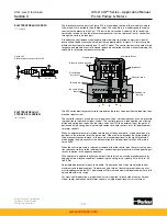
Page 44: ...ew functions are being used To reduce these horsepower losses and high heat loads the concept of load sensing has been devised Load sensing means that the pump output pressure will be set to the highest pressure required in the circuit at that instant in order to reduce the horsepower used When used in conjunction with the pressure compensator override of the GOLD CUP transmission pumps load sensi...

Page 45: ...g the modified valve block with no orifice in the sequence poppet with the addition of an orifice and a vent line as shown in the circuit in Figure 4 5 In this circuit the top of the compensator sequence valve see Circuitry Section 2 is con nected to the load side of the orifice by the vent line When the pressure drop through the orifice exceeds the pressure value of the spring on the sequence poppet t...

Page 46: ...hese losses include those of the gear boxes both pump drive and at the load and any other losses in the load drive mechanism If excess regenerated horsepower will be presented to the prime mover and all efforts to increase its absorption characteristics have been exhausted other methods of energy dissi pation must be employed For traction drives large manually operated service brakes may be used t...

Page 47: ...hey are introduced only as required If these flows are cooled and filtered they may be introduced continuously Unlike electric motors diesel engines are very reluctant to start under high loads especially when cold It is good practice to insure that the load is removed or disconnected prior to cranking Manual or electrically controlled clutches are sometimes used but are costly or inconvenient The G...

Page 48: ...mmediately shut it down or crank the engine without starting for 15 seconds Check for leaks 10 If possible start the unit and run at 1500 rpm or less If replenishment pressure fails to rise to 200 psi 13 8 bar within 30 seconds shut down otherwise idle for 15 minutes slowly stroke the pump in both directions to purge air from the lines If replenishment pressure drops off during stroking limit maxi...

Page 49: ...ould be protected from corrosion and capped or sealed before storage During machine assembly sub assemblies should be flushed to remove contaminant intro duced during the assembly process Caps and seals should be left on components tubes and hoses until just prior to making connections When filling reservoirs the fluid should be pumped through a series of filters to remove con taminants Filters for fil...

Page 50: ... for these limitations If these limits will be exceeded splined shafts must be used Because in many cases these applications would normally call for use of keyed shafts special consideration must be taken in the selection of the coupling Both shafts must be rigidly supported and properly aligned If the other shaft is splined a thru splined sleeve may be slipped over both shafts If the other shaft ...

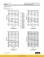
Page 51: ...07 in3 rev 17 5 cm3 rev auxiliary pump FULL STROKE 6 0 CIPR 98 3 CC REV 3 4 STROKE 4 5 CIPR 73 7 CC REV 1 2 STROKE 3 0 CIPR 49 2 CC REV 1 4 STROKE 1 5 CIPR 24 6 CC REV Vol Eff 1000 psi 69 bar Mech Eff 1000 psi 69 bar Overall Eff 1000 psi 69 bar Vol Eff 3000 psi 207 bar Mech Eff 3000 psi 207 bar Overall Eff 3000 psi 207 bar Vol Eff 5000 psi 345 bar Mech Eff 5000 psi 345 bar Overall Eff 5000 psi 345...

Page 52: ...ROKE 2 0 CIPR 32 8 CC REV Vol Eff 1000 psi 69 bar Mech Eff 1000 psi 69 bar Overall Eff 1000 psi 69 bar Vol Eff 3000 psi 207 bar Mech Eff 3000 psi 207 bar Overall Eff 3000 psi 207 bar Vol Eff 5000 psi 345 bar Mech Eff 5000 psi 345 bar Overall Eff 5000 psi 345 bar Vol Eff 1000 psi 69 bar Mech Eff 1000 psi 69 bar Overall Eff 1000 psi 69 bar Vol Eff 3000 psi 207 bar Mech Eff 3000 psi 207 bar Overall E...

Page 53: ... 07 in3 rev 17 5 cm3 rev aux pump FULL STROKE 7 25 CIPR 118 8 CC REV 3 4 STROKE 5 44 CIPR 89 1 CC REV 1 2 STROKE 3 62 CIPR 59 4 CC REV 1 4 STROKE 1 81 CIPR 29 7 CC REV Vol Eff 1000 psi 69 bar Mech Eff 1000 psi 69 bar Overall Eff 1000 psi 69 bar Vol Eff 3000 psi 207 bar Mech Eff 3000 psi 207 bar Overall Eff 3000 psi 207 bar Vol Eff 5000 psi 345 bar Mech Eff 5000 psi 345 bar Overall Eff 5000 psi 345...

Page 54: ...olume motor FULL STROKE 7 25 CIPR 118 8 CC REV 3 4 STROKE 5 44 CIPR 89 1 CC REV 1 2 STROKE 3 62 CIPR 59 4 CC REV 1 3 STROKE 2 42 CIPR 39 6 CC REV Vol Eff 1000 psi 69 bar Mech Eff 1000 psi 69 bar Overall Eff 1000 psi 69 bar Vol Eff 3000 psi 207 bar Mech Eff 3000 psi 207 bar Overall Eff 3000 psi 207 bar Vol Eff 5000 psi 345 bar Mech Eff 5000 psi 345 bar Overall Eff 5000 psi 345 bar RPM www comoso co...

Page 55: ... 1 07 in3 rev 17 5 cm3 rev aux pump FULL STROKE 8 0 CIPR 131 1 CC REV 3 4 STROKE 6 0 CIPR 98 3 CC REV 1 2 STROKE 4 0 CIPR 65 6 CC REV 1 4 STROKE 2 0 CIPR 32 8 CC REV Vol Eff 1000 psi 69 bar Mech Eff 1000 psi 69 bar Overall Eff 1000 psi 69 bar Vol Eff 3000 psi 207 bar Mech Eff 3000 psi 207 bar Overall Eff 3000 psi 207 bar Vol Eff 5000 psi 345 bar Mech Eff 5000 psi 345 bar Overall Eff 5000 psi 345 b...

Page 56: ... 2 STROKE 5 5 CIPR 90 1 CC REV 1 4 STROKE 2 25 CIPR 36 9 CC REV Vol Eff 1000 psi 69 bar Mech Eff 1000 psi 69 bar Overall Eff 1000 psi 69 bar Vol Eff 3000 psi 207 bar Mech Eff 3000 psi 207 bar Overall Eff 3000 psi 207 bar Vol Eff 5000 psi 345 bar Mech Eff 5000 psi 345 bar Overall Eff 5000 psi 345 bar RPM Section 5 PERFORMANCE CURVES Series 11 Variable volume pump with 2 14 in3 rev 35 cm3 rev aux pu...

Page 57: ...able volume motor FULL STROKE 11 CIPR 180 CC REV 3 4 STROKE 8 25 CIPR 135 CC REV 1 2 STROKE 5 5 CIPR 90 1 CC REV 1 3 STROKE 3 67 CIPR 60 1 CC REV Vol Eff 1000 psi 69 bar Mech Eff 1000 psi 69 bar Overall Eff 1000 psi 69 bar Vol Eff 3000 psi 207 bar Mech Eff 3000 psi 207 bar Overall Eff 3000 psi 207 bar Vol Eff 5000 psi 345 bar Mech Eff 5000 psi 345 bar Overall Eff 5000 psi 345 bar www comoso com ...

Page 58: ...th 2 14 in3 rev 35 cm3 rev aux pump FULL STROKE 14 CIPR 229 4 CC REV 3 4 STROKE 10 5 CIPR 172 CC REV 1 2 STROKE 7 CIPR 114 7 CC REV 1 4 STROKE 3 5 CIPR 57 4 CC REV Vol Eff 1000 psi 69 bar Mech Eff 1000 psi 69 bar Overall Eff 1000 psi 69 bar Vol Eff 3000 psi 207 bar Mech Eff 3000 psi 207 bar Overall Eff 3000 psi 207 bar Vol Eff 5000 psi 345 bar Mech Eff 5000 psi 345 bar Overall Eff 5000 psi 345 bar...

Page 59: ...ies 14 Variable volume motor FULL STROKE 14 CIPR 229 4 CC REV 3 4 STROKE 10 5 CIPR 172 CC REV 1 2 STROKE 7 0 CIPR 1 3 STROKE 4 67 CIPR Vol Eff 1000 psi 69 bar Mech Eff 1000 psi 69 bar Overall Eff 1000 psi 69 bar Vol Eff 3000 psi 207 bar Mech Eff 3000 psi 207 bar Overall Eff 3000 psi 207 bar Vol Eff 5000 psi 345 bar Mech Eff 5000 psi 345 bar Overall Eff 5000 psi 345 bar www comoso com ...

Page 60: ...h 2 81 in3 rev 46 cm3 rev aux pump FULL STROKE 24 66 CIPR 404 CC REV 3 4 STROKE 18 44 CIPR 303 CC REV 1 2 STROKE 12 33 CIPR 202 CC REV 1 4 STROKE 6 16 CIPR 101 CC REV Vol Eff 1000 psi 69 bar Mech Eff 1000 psi 69 bar Overall Eff 1000 psi 69 bar Vol Eff 3000 psi 207 bar Mech Eff 3000 psi 207 bar Overall Eff 3000 psi 207 bar Vol Eff 5000 psi 345 bar Mech Eff 5000 psi 345 bar Overall Eff 5000 psi 345 ...

Page 61: ...ble volume motor FULL STROKE 24 66 CIPR 404 CC REV 3 4 STROKE 18 5 CIPR 303 CC REV 1 2 STROKE 12 33 CIPR 202 CC REV 1 3 STROKE 8 22 CIPR 135 CC REV Vol Eff 1000 psi 69 bar Mech Eff 1000 psi 69 bar Overall Eff 1000 psi 69 bar Vol Eff 3000 psi 207 bar Mech Eff 3000 psi 207 bar Overall Eff 3000 psi 207 bar Vol Eff 5000 psi 345 bar Mech Eff 5000 psi 345 bar Overall Eff 5000 psi 345 bar www comoso com ...

Page 62: ...h 2 81 in3 rev 46 cm3 rev aux pump FULL STROKE 30 6 CIPR 501 4 CC REV 3 4 STROKE 23 CIPR 376 CC REV 1 2 STROKE 15 3 CIPR 250 7 CC REV 1 4 STROKE 7 6 CIPR 125 4 CC REV Vol Eff 1000 psi 69 bar Mech Eff 1000 psi 69 bar Overall Eff 1000 psi 69 bar Vol Eff 3000 psi 207 bar Mech Eff 3000 psi 207 bar Overall Eff 3000 psi 207 bar Vol Eff 5000 psi 345 bar Mech Eff 5000 psi 345 bar Overall Eff 5000 psi 345 ...

Page 63: ... 1 0 mm2 sec mm2 sec x 1 0 cSt SSU cSt x 4 25 14 20 cSt 99 SSU FLUID POWER FORMULAS Pump input torque lbs in pressure psi x displacement in3 rev 2 x mech eff Pump input power hp rpm x in3 rev x psi 395934 x overall eff Pump output flow U S gpm rpm x in3 rev x volumetric eff 231 Fluid motor speed rpm 231 x flow rate U S gpm x volumetric eff displacement in3 rev Fluid motor torque lbs in pressure psi ...

Page 64: ... Circuit M Fixed Displacement with High Torque Thru Drive Open Closed Circuit P Variable Displacement Closed Circuit X Variable Displacement with Medium Torque Thru Drive Closed Circuit S Variable Displacement with Medium Torque Thru Drive Shuttle Package Closed Circuit R Variable Displacement with High Torque Thru Drive Closed Circuit L Variable Displacement with High Torque Thru Drive Shuttle Pa...

Page 65: ...al Modifications Control Code Control Feature 2M 2N 00 CETOP3 NG6 Valve 110AC 60Hz with Hirschmann Connector 1 01 CETOP3 NG6 Valve 12VDC with Hirschmann Connector 1 02 CETOP3 NG6 Valve 240VAC 50Hz with Hirschmann Connector 1 03 CETOP3 NG6 Valve 110VAC 60Hz Wiring Box 1 04 CETOP3 NG6 Valve 12VDC Wiring Box 1 05 CETOP3 D03 NG6 Interface No Valve 1 06 CETOP3 NG6 Valve 24VDC with Hirschmann Connector 1...

Page 66: ...fficiency M24 only Omit Standard Efficiency Type Code Rotation N Bi directional Code Seals 1 Nitrile Buna N 4 EPR 3 5 Fluorocarbon Design2 Code Primary Controls Omit None Fixed Displacement only 2A Cylinder Control w Adjustable Maximum Volume Stops 2M Cylinder Control 2 Position Electrohydraulic w Ad justable Maximum Volume Stop Spring Offset to Maximum Displacement 1 5A Electrohydraulic Stroker w A...

Page 67: ...6 Valve 12VDC Wiring Box1 5 CETOP3 D03 NG6 Interface No Valve1 6 CETOP3 NG6 Valve 24VDC with Hirschmann Connector1 7 CETOP3 NG6 Valve 110VAC 50Hz with Hirschmann Connector1 5A 0 With Deadband1 1 Without Deadband1 8A 0 75 250 PSI 5 17 Bar 1 250 450 PSI 17 31 Bar 9A 0 24VDC1 1 12VDC1 All Other 0 None Motor Code Reduced Displacement M F M G M M M N 0 Standard Cam 19 1 M6 with 17 Cam 5 3 in3 rev 87cc ...

Page 68: ...4 05 4B6 7J6 01 8A6 02 2M4 06 2N4 06 5C2 00 8A6 03 9C2 00 2H8 2M4 07 2N4 07 4B8 5C2 01 8A6 04 9C2 01 2M6 00 2N6 00 4C2 5C4 00 9C4 00 2M6 01 2N6 01 4C4 5C4 01 7J8 00 9C4 01 2M6 02 2N6 02 4C6 7J8 01 8C8 00 2M6 03 2N6 03 5C6 00 8C8 01 9C6 00 2M6 04 2N6 04 4C8 5C6 01 7K6 01 8C8 02 9C6 01 2M6 05 2N6 05 8C8 03 2M6 06 2N6 06 7K8 01 8A8 00 2M6 07 2N6 07 8A8 01 8A8 02 5C8 00 8A8 03 9C8 00 5C8 01 8A8 04 9C8...

Page 69: ...8A5 0 9A5 0 2M0 0 5A5 1 8A5 1 9A5 1 2M0 1 2M0 2 2M5 0 5A6 0 8A6 0 9A6 0 2M0 3 2M5 1 5A6 1 8A6 1 9A6 1 2M0 4 2M5 2 2M0 5 2M5 3 2M0 6 2M5 4 2M5 5 2M5 6 5A8 0 8A8 0 9A8 0 5A8 1 8A8 1 9A8 1 2M6 0 9D0 0 2M6 1 9D081 2M6 2 2M6 3 2M6 4 2M6 5 2M6 6 s OT AVAILABLE FOR OR Unless otherwise specified on purchase order the following factory setting will be used Maximum Stop Full Displacement Minimum Stop Approx...

Page 70: ...HY28 2668 01 GC NA EU GOLD CUP Series Application Manual Piston Pumps Motors 7 1 Parker Hannifin Corporation Hydraulic Pump Division Marysville Ohio USA Notes Notes www comoso com ...

Page 71: ...ing to Seller which is utilized in the manufacture of the Products even if such apparatus has been specially converted or adapted for such manufacture and notwithstanding any charges paid by Buyer Unless otherwise agreed Seller shall have the right to alter discard or otherwise dispose of any special tooling or other property in its sole discretion at any time 11 Buyer s Obligation Rights of Selle...

Page 72: ...Slovakia Klecany Tel 420 284 083 111 Denmark Ballerup Tel 45 4356 0400 Finland Vantaa Tel 358 20 753 2500 France Contamine sur Arve Tel 33 4 50 25 80 25 Germany Kaarst Tel 49 2131 4016 0 Greece Athens Tel 30 210 933 6450 Hungary Budapest Tel 36 1 220 4155 Ireland County Dublin Baldonnell Tel 353 1 466 6370 Italy Corsico Milano Tel 39 02 45 19 21 The Netherlands Oldenzaal Tel 31 541 585000 Norway S...

Reviews: