HY28-2668-01/GC/NA,EU
GOLD CUP
®
Series - Application Manual
Piston Pumps & Motors
1.3
Parker Hannifin Corporation
Hydraulic Pump Division
Marysville, Ohio USA
Section 1
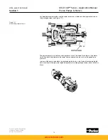
Flow into the upper and lower vane chambers is carried in a pair of small channels drilled into
the rocker cam (see Figure 1.1). Figure 1.4 shows the servo stems which are bolted to the
rocker cam on both sides. Channels run through the length of the servo stem and depressions
in the end of the stem connect the upper channel in the stem to the lower vane chambers and
vice versa. Orifice plugs in the servo stem limit the flow rate into and out of the vane cham-
bers and therefore the stroking rate.
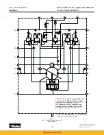
A flat servo plate is bolted to the servo stem on the control side of the pump and a flat bal-
ance plate is bolted to the servo stem on the output (displacement indicator ) side of the pump
(see Figure 1.5). The servo plate has two holes which connect directly to the channels in the
servo stem while the balance plate is blank and plugs the end of its servo stem. Because
the servo stems and plates are bolted to the rocker cam, they all move with the cam during
displacement changes.
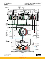
The vane chambers are sealed by covers which also form the fourth surface for the vane to
seal against. In the covers are channels to carry the flow from the pressure compensator
override tubes to the proper stroking vane chambers. The vane chamber cover on one side of
the pump will port flow into one set of vane chambers (either upper or lower) while the cover
on the opposite side ports flow into the other chambers. Figure 1.6 shows the vane cham-
ber covers and the internal porting. Vane chamber cover porting will change with rotation as
shown.
Figure 1.4
GOLD CUP
®
pump internal
configuration vane chambers and
servo stems
Figure 1.5
GOLD CUP
®
pump internal
configuration vane chamber
covers and servo plates
Figure 1.6
Vane chamber covers
www.comoso.com


