9
3.2 Connecting the generator
Refer to “Recommended system layout” on page 8 for the desired system configuration.
Apply eight turns of PTFE tape to the threads of the compression fittings supplied. Remove the labels covering the ports of the filters and insert
the fittings.
1
Connect the generator to the air supply through a pressure relief valve, pressure regulator and an isolation valve. Leave the valve in the
closed position at this time. The pressure relief valve should be set at 11 bar g.
2
Fit a flow control valve, non-return valve and 3 way ball valve with silencer to the outlet filter of the generator.
Connect the ball valve to the application using clean stainless steel or pre-cleaned refrigeration grade copper tubing and fittings.
The tubing and fittings should be suitable for the application and rated to at least the maximum operating pressure of the generator.
3.2.1 Electrical supply
Check the rating plate for the correct supply voltage and frequency. Select the required power cord and connect it to the switched IEC 320
socket on the generator. Connect the plug directly to the electrical supply. Do not use an extension cord.
3.2.2 Stacking the Generator
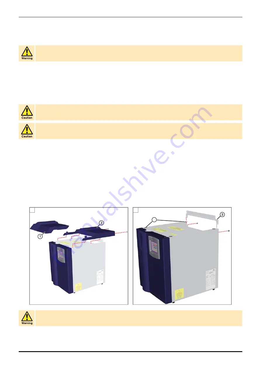
The generator may be re-configured so that the Parker Hannifin H and HMD range of hydrogen generators may be stacked safely on top of it.
To re-configure the generator, unlock the two retaining screws and remove the top service lid panel (1). Remove the two retaining screws on the
rear of the top lid panel (2). Slide the panel backwards until the nylon locating screws are free from their retaining slots and remove the panel.
Remove the two screws holding the rear bracket in place. Lift the bracket away from the assembly and store it safely along with the top cover.
Position the hydrogen generator on to the zero air generator.
Note.
The rubber feet on the hydrogen generator must be positioned in the locating holes (4) on the zero air generator chassis.
Ensure that the air supply and application piping are connected to the correct ports on the rear of the generator. Failure to
observe the correct orientation could lead to excessive temperatures, burns, or fire.
Do not use plastic tubing to connect the generator to the application as this could cause contamination of the zero air.
Use PTFE on the BSPT fittings. Do not use sealing compounds as they could cause contamination of the zero air.
The upper plate is designed to withstand a maximum load of 30 kg (66lb). Do not place any objects other than the Parker Hannifin hydrogen
generator on this plate.
4
A
B
Summary of Contents for domnick hunter UHP10ZA-S
Page 4: ......


