17
DUSTHOG PNP Series
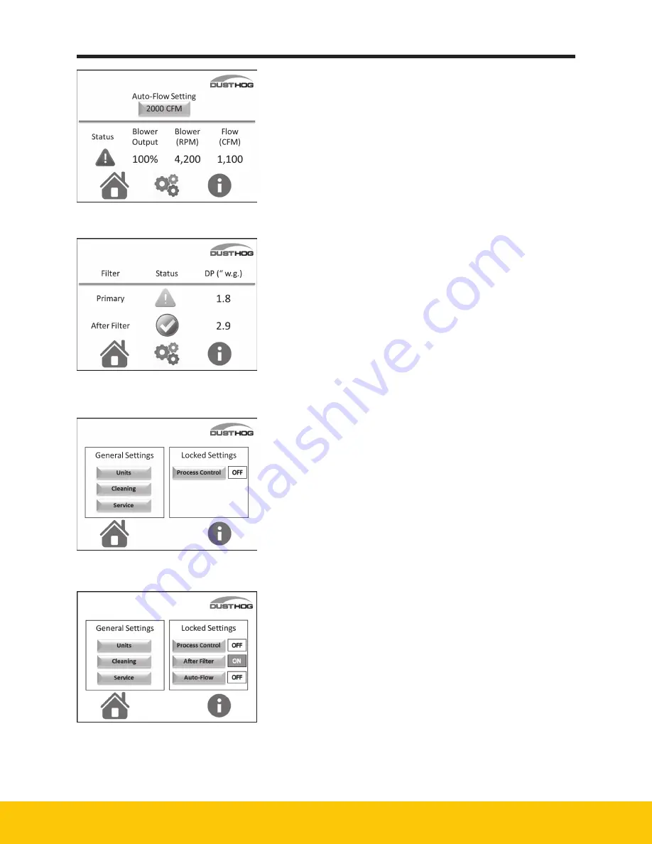
Figure 11 - Auto-Flow screen
Figure 12 - After-Filter Screen
Figure 13 -
Customer Settings Screen
Figure 14
4.3.4 Auto-Flow screen
When Auto-Flow is installed and activated the blower screen
will look like Figure 11. Refer to section 4.3.6 to activate the
Auto-Flow option and to make adjustments to your flow target.
The Auto-Flow blower screen will show the target flow, the
actual flow, the blower speed, and the % of total speed
available. The screen will also show blower status.
If there is a warning or fault, refer to the troubleshooting
section for guidance.
4.3.5 After-Filter
When the screen is active you will see the differential
pressure across the filter. The system will monitor this
pressure and give warnings and faults as the differential
pressure changes. The after-filter does not get cleaned by
the system and has a finite life based on the pressure drop
across the filter. When the pressure drop increases to a point
that the filter can no longer provide proper airflow, the fault
symbol will appear. The customer will need to replace the filter
at that time.
4.3.6 Customer Settings
The standard customer settings screen shown in Figure 13
will allow the operator to make General Setting changes
without a password. The Locked Settings will require a
password to be entered. The password is 4440.
The General Settings selection will allow the operator to
change the units, the cleaning settings, and check service
of the major components (blower and pulse valves).
These settings are not password protected. To select one of
the items just touch the box with the item you want to make
a change to.
The Locked Settings selection will allow the operator to
select options of the system. One option is Process Control.
With Process Control the operator can allow another device
(CNC machine center, plasma table, or weld machine) to turn
the PNP on when the primary device is in operation.
When this option is selected the Blower Power button in
Figure 6, will put the unit in standby when touched by the
operator. When this setting is selected the indicator to the
right side will change from OFF to ON and turn green.
When After-Filter and/or Auto-Flow options are ordered, they
will appear on the Customer Settings screen as shown on
Figure 14.
When the units selection is made on the Customer Settings
screen, you will see the screen as shown on Figure 15.
Figure 14
Summary of Contents for DUSTHOG PNP
Page 1: ...DUSTHOG Plug Play Fume Dust Collector Owner s Manual Model PNP...
Page 6: ...Page intentionally left blank...
Page 11: ...7 DUSTHOG PNP Series 61 10121 Figure 2 PNP Weights and Lifting Info...
Page 27: ...23 DUSTHOG PNP Series Page intentionally left blank...
Page 29: ...25 DUSTHOG PNP Series PNP 12 Figure 24 PNP Replacement Parts 61 10123...
Page 30: ...26 DUSTHOG PNP Series A1 Transformer 575 480 8 Appendix Wiring Diagrams 04 001886...
Page 31: ...27 DUSTHOG PNP Series A2 One Blower Controls 04 001830...
Page 32: ...28 DUSTHOG PNP Series A3 Two Blower Controls 04 001831...
Page 33: ...29 DUSTHOG PNP Series A4 Three Blower Controls 04 001832...
Page 34: ...30 DUSTHOG PNP Series A5 Four Blower Controls 04 001881...
Page 35: ...31 DUSTHOG PNP Series A6 Remote Panel Controls 04 001868...
Page 36: ...32 DUSTHOG PNP Series A7 One Blower Remote Controls 04 001833 A7...
Page 37: ...33 DUSTHOG PNP Series A8 A8 Two Blower Remote Controls 04 001834...
Page 38: ...34 DUSTHOG PNP Series A9 Three Blower Remote Controls 04 001863...
Page 39: ...35 DUSTHOG PNP Series A10 Four Blower Remote Controls 04 001864...


