background image

Axial Piston Pumps

Series eP2 / eP3 – Electronic Controls

5

Parker Hannifin Manufacturing Germany GmbH & Co. KG

Pump & Motor Division Europe
Chemnitz, Germany

Installation and setup manual

Bulletin MSG30-2901-INST/UK

2.3. Electrical interfaces, PIN assignment

Check voltage, current, phase and connection prop-
erties before plugging in any electrical component.
Following mating connectors need to be used to 
connect the actuator and sensors properly.

Electrical  

component

Connector

Mating 

Connector

Valve

DT04-2P

DT06-2S

Swash angle sensor

DT04-3P

DT06-3S

Pressure Sensor

DT04-4P

DT06-4S

With correctly installed and mounted mating con-
nector all “DEUTSCH” connectors used meet 
protection class IP 67.

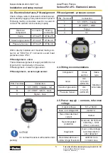
PIN assignment - valve:

The terminal assignment of supply and GND is not 
important for functionality of the valve.
PIN assignment – swash angle sensor:

PIN assignment – swash angle sensor:

PIN / Terminal

Connection

A

5V / VREF+ / Supply – red

B

0V / VREF- / GND – black

C

Signal – blue

NOTICE

Do not treat the sensor with electro static

painting.

PIN assignment - pressure sensor:

PIN / Terminal

Connection

1

5V / VREF+ / Supply

2

0V / VREF- / GND

3

Signal

4

n.c.

2.4. Wiring recommendations

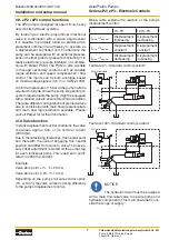
2.5.  Power supply – sensors, reference 

voltage

Component

Cross 

section

Cable 

type

Valve

min. 

0,75 mm² 

(AWG 18)

Stranded 

wire cable

Swash angle sensor

min. 

0,5 mm²

(AWG 20)

Pressure Sensor

Output voltage

5V ± 150mV

Max. out voltage drift

0,5mV/°C

Recommended load 

current

150mA

Recommended 

protection

Overload, SCB (Short 

to Battery) , SCG 

(Short to Ground)

Diagnostic

Over-/ undervoltage 

recommended for 

error detection

Recommended over-/ 

undervoltage threshold

±500mV from 

nominal value

Summary of Contents for eP2 Series

Page 1: ...Bulletin MSG30 2901 INST UK Installation and setup manual Series eP2 eP3 Electronic Controls Effective March 01 2019 Supersedes March 01 2018 Visit our homepage for additional support parker com pmde ...

Page 2: ... recommendations 5 2 5 Power supply sensors reference voltage 5 2 6 Sensor properties 6 2 7 Valve properties 6 2 8 Electrical displacement adjustment 6 2 9 eP2 eP3 control functions 7 2 10 Valve function 7 2 11 Typical arrangements eP2 8 2 12 Typical arrangement eP3 8 2 13 Fluid reservoir 9 2 14 Hydraulic system safety 9 3 Hydraulic fluid requirements 9 3 1 Recommended fluids 9 3 2 Cleanliness lev...

Page 3: ...e for component failure Therefore maximum care and cleanliness are required during all handling of parts which are in contact with the hydraulic fluid All ports of the pump must be covered plugged until the connectors and hoses are mounted Perform assembly preferably in a dry and dust free room Use only suitable tools 2 Installation 2 1 Drive input Please strictly follow the instructions of the co...

Page 4: ...d logged in case the measured pump pressure exceeds respective limitations Drain port Always use highest possible drain port of the pump above pump s centerline Do not combine drain lines Use low pressure pipe hose as short as possible and full cross section according to port dimension see MSG30 2800 MSG30 2900 Do not use elbows or sharp cor ners To prevent the pump s case from emptying add a brid...

Page 5: ...ment valve The terminal assignment of supply and GND is not important for functionality of the valve PIN assignment swash angle sensor PIN assignment swash angle sensor PIN Terminal Connection A 5V VREF Supply red B 0V VREF GND black C Signal blue NOTICE Do not treat the sensor with electro static painting PIN assignment pressure sensor PIN Terminal Connection 1 5V VREF Supply 2 0V VREF GND 3 Sign...

Page 6: ...nt All axial piston pumps of series eP2 are equipped with an adjusted and sealed displacement limiter Do not change this setting Maximum displacement should be limited electronically The factory setting is at 101 of the nominal pump displacement Therewith the mechanical displace ment limiter is 1 out of the pumps electronic controlled working range This prevents the control from running into bound...

Page 7: ...rations of preload valves also in combination with main flow pressure reliefs and main flow logic elements available Please consult Parker for further information 2 10 Valve function In static displacement control conditions the valve consumes approx 53 of its nominal current 2200 mA Due to manufacturing tolerances this neutral point and therewith the current engaging this neutral position can dif...

Page 8: ...ST UK 2 11 Typical arrangements eP2 Please consult Parker for deviating approaches 2 12 Typical arrangement eP3 Please consult Parker for deviating approaches Preferred arrangement for best suction character istics and low noise level operation Preferred arrangement for best suction character istics and low noise level operation 0 2 m MIN 0 8 m MAX 0 2 m MIN 0 15 m MIN 0 2 m MIN 0 8 m MAX 0 15 m M...

Page 9: ...ystem 3 Hydraulic fluid requirements 3 1 Recommended fluids Hydraulic fluids based on mineral oils acc to DIN 51524 part 2 and 3 HLP HVLP Pumps of series P2 P3 can also be operated with environmentally acceptable bio degradable and synthetic hydraulic fluids Please consult Parker for further details 3 2 Cleanliness level For maximum component life and reliability a cleanliness level of 18 16 13 ac...

Page 10: ...outine Continuous monitoring Operating temperature noise levels vibration Daily check up Oil level and frothing in reservoir pump leakage Monthly check up Fixtures Yearly Oil check viscosity contamination wear Check swash angle sensor calibration recalibrate if necessary 5 Trouble Shooting Component problems and circuit problems are often interrelated An improper circuit may oper ate with apparent...

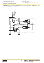
Page 11: ... setup manual Bulletin MSG30 2901 INST UK 6 Appendix System Layout with pump control module PCM Displacement control Displacement control with pressure monitoring or pressure cut off and optional torque limitation PCM A P T P A T U R V not included out analogue Mout Min in ɑ or CAN BUS J1939 p PCM A P T P A T U R V not included out analogue Min in ɑ or CAN BUS J1939 ...

Page 12: ...ing Germany GmbH Co KG Pump Motor Division Europe Chemnitz Germany Bulletin MSG30 2901 INST UK Displacement control with pressure monitoring or pressure cut off and optional torque limitation as well as speed compensation flow control p rpm PCM A P T P A T U R V not included out analogue Min in ɑ or CAN BUS J1939 ...

Page 13: ...its subsidiaries or authorized distributors provide component or system options based upon data or specifications provided by the user the user is responsible for determining that such data and specifications are suitable and sufficient for all applications and reasonably foreseeable uses of the components or systems Offer of Sale Please contact your Parker representation for a detailed Offer of S...

Page 14: ...contact Parker Hannifin Manufacturing Germany GmbH Co KG MSG30 2901 INST UK Pump and Motor Division Europe Neefestraße 96 09116 Chemnitz Germany Tel 49 0 371 3937 0 Copyright 2019 Fax 49 0 371 3937 488 All rights reserved Email pmde pqd support parker com parker com pmde ...

Reviews: