background image


– Pvd3665_Gb_Ex_August 2022 


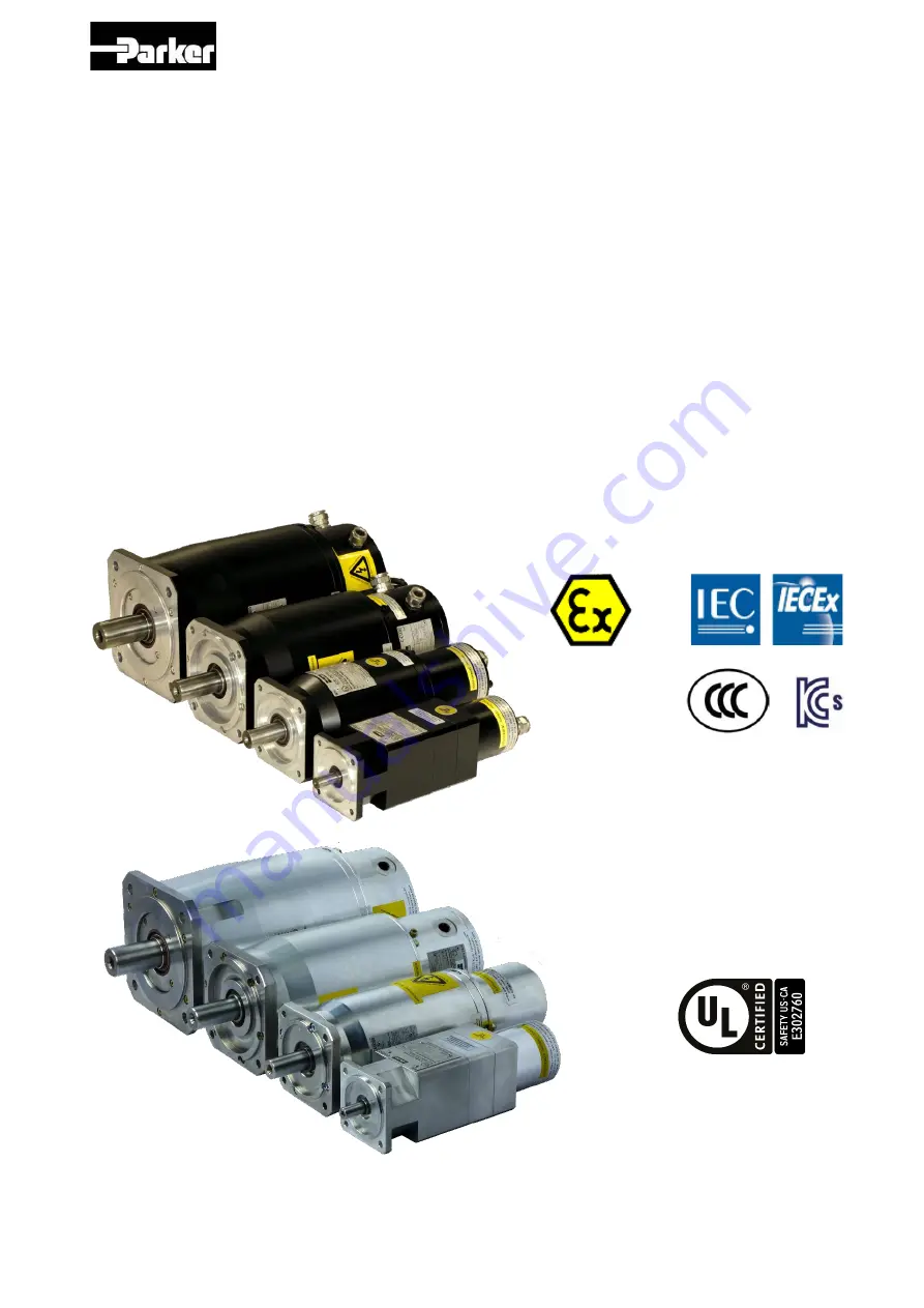
Servomotors 


EX Series 


Technical Manual 


PVD 3665 - EX 


Summary of Contents for EX Series

Page 1: ...1 Pvd3665_Gb_Ex_August 2022 Servomotors EX Series Technical Manual PVD 3665 EX...

Page 2: ...2 Pvd3665_Gb_Ex_August 2022...

Page 3: ...3 Pvd3665_Gb_Ex_August 2022...

Page 4: ...4 Pvd3665_Gb_Ex_August 2022...

Page 5: ...5 Pvd3665_Gb_Ex_August 2022...

Page 6: ...6 Pvd3665_Gb_Ex_August 2022...

Page 7: ...7 Pvd3665_Gb_Ex_August 2022...

Page 8: ...8 Pvd3665_Gb_Ex_August 2022...

Page 9: ...9 Pvd3665_Gb_Ex_August 2022...

Page 10: ...10 Pvd3665_Gb_Ex_August 2022...

Page 11: ...11 Pvd3665_Gb_Ex_August 2022...

Page 12: ...12 Pvd3665_Gb_Ex_August 2022...

Page 13: ...13 Pvd3665_Gb_Ex_August 2022...

Page 14: ...14 Pvd3665_Gb_Ex_August 2022...

Page 15: ...15 Pvd3665_Gb_Ex_August 2022...

Page 16: ...16 Pvd3665_Gb_Ex_August 2022...

Page 17: ...17 Pvd3665_Gb_Ex_August 2022...

Page 18: ...18 Pvd3665_Gb_Ex_August 2022...

Page 19: ...19 Pvd3665_Gb_Ex_August 2022 Compliance with UL standards...

Page 20: ...20 Pvd3665_Gb_Ex_August 2022 Compliance with UL standards...

Page 21: ...1 2 Altitude derating _______________________________________________________________________ 41 3 1 3 Temperature derating ___________________________________________________________________ 41 3 1...

Page 22: ..._____________________ 85 3 4 1 Motor mounting________________________________________________________________________ 85 3 4 2 Installation of ATEX machines ___________________________________________...

Page 23: ..._________________121 4 1 3 Storage ______________________________________________________________________________122 4 2 Installation __________________________________________________________________...

Page 24: ...case of missing information or doubts regarding the installation procedures safety instructions or any other issue tackled in this manual please contact PARKER as well PARKER s responsibility is limit...

Page 25: ...fication is based on IECEx certification The Kosha EX motors are also IECEx Kosha IECEx certified have a limited number of options indicated in the next tables DANGER All the instructions for the IECE...

Page 26: ...5 Product series EX Motor size 3 Motor length 10 1 1 2 3 4 5 6 7 8 9 10 11 E X 3 1 0 E Code 1 2 3 4 5 6 7 8 9 10 11 Product series EX Motor size 4 5 6 7 8 9 10 11 R Hiperface encoder singleturn SKS36...

Page 27: ...brake 5 With brake Mechanical interface 00 IP64 Plain shaft Name plate IECEx 10 IP64 key on shaft 10 IP65 Plain shaft 11 IP65 key on shaft Code 1 2 3 4 5 6 7 8 9 10 11 E X 8 E 1 Product series EX Mot...

Page 28: ...ANGER All the instructions for the IECEx motors shall be applied to CCC motors in addition to the local regulation the standards GB3836 1 2010 GB3836 2 2010 GB12476 1 2013 GB12476 5 2013 the CNCA C23...

Page 29: ...otor Product series EX Motor size 3 6 7 8 9 10 11 1 C 1 2 3 4 5 E X 3 1 0 E Code 1 2 3 4 5 6 7 8 9 10 11 Name plate C CCC 10 IP65 Plain shaft 11 IP65 key on shaft Mechanical interface 00 IP64 Plain sh...

Page 30: ...SIL2 Motor length 20 30 Motor version E ATEX IECEx CCC motor 10 11 Product series EX Motor size 6 C 1 2 3 4 5 6 7 8 9 1 E X 6 E Code 1 2 3 4 5 6 7 8 9 10 11 11 IP65 key on shaft Name plate C CCC 10 IP...

Page 31: ...inst access to live parts before installing the equipment Some parts of the motor or installation elements can be subjected to dangerous voltages when the motor is driven by the inverter when the moto...

Page 32: ...in mind that some parts of the surface of the motor can reach a temperature of 135 C Atex servomotors This motor can be used in hazardous areas May particular attention to the notes marked with Europ...

Page 33: ...with a thermal protection which is checked by a safety analysis and is a key element of the ATEX IECEx safety It is possible to connect this protection to the unlocked input or through a safety syste...

Page 34: ...l of protection IP64 M2 High level of protection p Pressurized apparatus T2 300 C Mb High level of protection II Surface 1 Very high level of protection db Flameproof enclosure II Surface Gas A Propan...

Page 35: ...sing in dusty explosive atmospheres the user must perform regular cleaning operations on the motor to avoid dust deposits II 2 D Ex tb III C T135 C Db IP65 I Mines M1 Very high level of protection D C...

Page 36: ...Class I Gaz vapours ou liquids Division 1 Explosive atmospheres can exist all the time or some of the time under normal operating conditions A Acetylene T1 450 C IP65 B Hydrogen T2 300 C T3 200 C C Et...

Page 37: ...nment conditions A large set of torque speed characteristics options and customization possibilities are available making EX servomotors the ideal solution for most servosystems applications in explos...

Page 38: ...winding Class F according to IEC 60034 1 Class F according to IEC 60034 1 with potting Altitude Up to 1000m IEC 60034 1 No allowed for higher altitude Ambiant temperature 20 C to 40 C 20 C to 60 C wi...

Page 39: ...nsulation of the stator winding Class F according to IEC 60034 1 Class F according to IEC 60034 1 with potting Altitude Up to 1000m IEC 60034 1 Ambiant temperature 20 C to 40 C Storage temperature 20...

Page 40: ...nd on size Motor version E ATEX IECEx motor U UL motor Feedback Sensor A resolver 2 poles transformation ratio 0 5 P DSL encoder singleturn EKS36 SIL2 Not for UL Q DSL encoder multiturn EKM36 SIL2 Not...

Page 41: ...than 60 C a derating of performances is applied according to data recommended by Parker 3 1 4 Thermal equivalent torque rms torque The selection of the right motor can be made through the calculation...

Page 42: ...i Selection of the motor The motor adapted to the duty cycle has to provide the rms torque Mrms at the rms speed without extra heating This means that the permanent torque Mn available at the average...

Page 43: ...rque vs speed curve Torque Mk Mrms Mn Mi i k rms n Speed 3 1 5 Servo drive selection Selection of drive depends on its rated power rated current and its mode selection which leads to the maximal curre...

Page 44: ...ode is used for induction motors while Servo mode is used for brushless AC motors With EX motors the power is usually 37 kW the rated current corresponds to 100 Power of Drive AC890 kW 37 kW Mode Serv...

Page 45: ...he motor is 5 51 Arms for M0 7 Nm at low speed The nominal current In of the motor is 2 46 Arms for Mn 3 13 Nm at the nominal speed Selection of the drive The drive has to provide at least a permanent...

Page 46: ...itivity is equals to 1 27 Nm Arms Selection of the drive The drive has to provide a permanent current equals to 4 Arms to obtain 5 Nm In order to obtain an acceleration torque of 7 6 Nm the current wi...

Page 47: ...sible to use the EX motor with a current higher than the permanent current But to avoid any overheating the following rules must be respected 1 The peak currents and peak torques given in the data she...

Page 48: ...teristics Torque speed current power The torque vs speed graph below explains different intrinsic values of the next tables Torque Peak Torque Permanent Low Speed Torque Rated torque Stall torque 3 rp...

Page 49: ...2200 7 5 14 9 3 32 5 23 2 2200 EX840EAK 3 31 15 8 2000 9 4 24 5 14 3 58 2 35 6 2000 EX860EAJ 3 86 25 4 1450 11 5 35 15 7 83 3 39 2 1450 Motor Rated Power Rated Torque Rated Speed Rated Current Low Sp...

Page 50: ...14 9 3 32 5 23 2 3900 EX840EAK 0 99 2 9 3300 2 1 24 5 14 3 58 2 35 6 3500 EX860EAJ 2 35 9 0 2500 4 4 35 15 7 83 3 39 2 2600 Motor Rated Power Rated Torque Rated Speed Rated Current Low Speed Torque L...

Page 51: ...2 8 2300 EX840UAL 2 90 16 8 1650 9 0 23 12 0 56 5 32 3 1650 EX860UAJ 3 50 22 3 1500 10 0 31 13 9 78 5 37 1 1500 3 2 4 UL 400V Motor Rated Power Rated Torque Rated Speed Rated Current Low Speed Torque...

Page 52: ...26 10 75 7 EX620EAV 2 78 180 67 6 7 9 980 10 137 EX620EAR 1 48 95 7 19 2 2 24 980 10 137 EX630EAR 2 27 138 24 9 2 43 1470 10 158 EX630EAN 1 5 91 6 10 9 1 12 1470 10 150 EX820EAR 1 51 93 8 57 1 01 3200...

Page 53: ...s are typical values They may vary from one motor to an other Caution The efficiency curves are given for an optimal motor control no voltage saturation and optimal phase between current and EMF Cauti...

Page 54: ...6 4 6 4 6 4 64 64 64 6 6 6 6 6 6 66 66 66 6 8 6 8 6 8 68 68 68 7 0 7 0 7 0 70 70 70 7 2 7 2 7 2 72 72 72 7 4 7 4 7 4 74 74 74 76 76 7 6 7 6 76 76 78 78 78 7 8 78 78 78 80 80 80 80 80 80 80 82 82 82 8...

Page 55: ...0 90 90 92 Constant efficiency curves of the motor EX420E Speed rpm Torque Nm 0 500 1000 1500 2000 2500 3000 3500 4000 0 1 2 3 4 5 6 7 8 Efficiency 50 50 50 50 50 50 52 52 52 52 52 52 54 54 54 54 54 5...

Page 56: ...94 9 4 94 Constant efficiency curves of the motor EX620E Speed rpm Torque Nm 0 500 1000 1500 2000 2500 3000 3500 4000 0 2 4 6 8 10 12 14 16 Efficiency 50 50 50 50 50 50 52 52 52 52 52 52 54 54 54 54 5...

Page 57: ...92 92 92 9 4 Constant efficiency curves of the motor EX820E Speed rpm Torque Nm 0 500 1000 1500 2000 2500 3000 3500 0 5 10 15 20 25 30 35 Efficiency 50 50 50 50 50 50 52 52 52 52 52 52 54 54 54 54 54...

Page 58: ...6 66 6 6 66 66 66 6 8 68 6 8 68 68 68 7 0 70 70 70 70 70 7 2 7 2 72 72 72 72 7 4 7 4 74 74 74 74 7 6 7 6 76 76 76 76 7 8 7 8 78 78 78 78 8 0 8 0 8 0 80 80 80 8 2 8 2 8 2 82 82 82 8 4 8 4 8 4 84 84 84...

Page 59: ...64 6 6 6 6 66 66 66 66 6 8 6 8 68 68 68 68 7 0 7 0 70 70 70 70 7 2 7 2 7 2 72 72 72 7 4 7 4 7 4 74 74 74 7 6 7 6 7 6 76 76 76 7 8 7 8 7 8 78 78 78 8 0 8 0 8 0 80 80 80 8 2 8 2 8 2 82 82 82 8 4 8 4 8 4...

Page 60: ...92 92 92 92 92 Constant efficiency curves of the motor EX420U Speed rpm Torque Nm 0 1000 2000 3000 4000 5000 6000 7000 0 1 2 3 4 5 6 7 8 Efficiency 50 50 50 50 50 50 52 52 5 2 52 52 52 54 54 54 54 54...

Page 61: ...94 94 Constant efficiency curves of the motor EX620U Speed rpm Torque Nm 0 500 1000 1500 2000 2500 3000 3500 4000 4500 5000 0 2 4 6 8 10 12 14 16 Efficiency 50 50 5 0 50 50 50 52 52 52 52 52 52 54 54...

Page 62: ...92 92 92 94 94 Constant efficiency curves of the motor EX820U Speed rpm Torque Nm 0 500 1000 1500 2000 2500 3000 3500 4000 0 5 10 15 20 25 30 Efficiency 50 50 5 0 50 50 50 52 52 52 52 52 52 54 54 54 5...

Page 63: ...66 66 66 66 66 66 68 6 8 68 68 68 68 7 0 70 70 70 70 70 7 2 72 72 72 72 72 7 4 7 4 74 74 74 74 7 6 7 6 76 76 76 76 7 8 7 8 78 78 78 78 8 0 8 0 80 80 80 80 8 2 8 2 8 2 82 82 82 8 4 8 4 8 4 84 84 84 8...

Page 64: ...o responsibility will be accepted for direct or indirect losses or damages due to the use of these data Following data are indicative without lip seal IP64 motor Type Tf Nm Kd Nm 1000rpm EX310EAP 0 06...

Page 65: ..._ _ _ _ _ ph ph ph ph ph ph n ph n ph mech Ke Ke J R Ke Kt J R 2 _ _ 5 0 ph ph ph ph mech Ke J R With following values obtained from the motor data sheet Rph_ph resistance of the motor phase to phase...

Page 66: ...rall summary of motor time constants is given a little further 3 2 8 3 Thermal time constant of the copper copper therm Cth Rth 389 K kg J Kg copper K J copper Mass Cth With Rth thermal resistance bet...

Page 67: ...drive gains of both speed and current regulation loops presence of filtering or not load inertia resistant torque and type of sensor in use without external load neither external inertia nor resistant...

Page 68: ...the rated values will also change As long as the variation of the rated voltage remains limited for instance to 10 of the nominal value it is possible to correctly evaluate the new rated values as ill...

Page 69: ...the drive still shows able to deal with the new maximum electric frequency Warning If the main supply decreases you must reduce the maximum speed accordingly in order to do not damage the motor In cas...

Page 70: ...ommendations of the IEC TS 60034 25 ed 2 0 2007 03 12 for motors without filters up to 500V AC See figure 1 Figure 1 Minimum Voltage withstands characteristics for motors insulations according to IEC...

Page 71: ...Power supply direct current voltage V 310 10 550 10 Motor electrical frequency Hz 0 to 500 0 to 500 Steady peak current in a phase Arms Max 25 17 7 Max 16 11 3 Maximum peak current in a phase Arms Max...

Page 72: ...rrent in a phase Arms Max 28 19 8 Max 16 11 3 Maximum steady motor power W Max 3400 Max 3400 EX6 UL Voltage of the associated speed drive 230V single three phases 400 480V three phases Nominal Power s...

Page 73: ...73 Pvd3665_Gb_Ex_August 2022 3 3 Dimension drawings 3 3 1 EX310E...

Page 74: ...74 Pvd3665_Gb_Ex_August 2022 3 3 2 EX420E EX430E...

Page 75: ...75 Pvd3665_Gb_Ex_August 2022 3 3 3 EX620E EX630E...

Page 76: ...76 Pvd3665_Gb_Ex_August 2022 3 3 4 EX820E EX840E EX860E...

Page 77: ...77 Pvd3665_Gb_Ex_August 2022 3 3 5 EX310 C CCC...

Page 78: ...78 Pvd3665_Gb_Ex_August 2022 3 3 6 EX420 C EX430 C CCC...

Page 79: ...79 Pvd3665_Gb_Ex_August 2022 3 3 7 EX620 C EX630 C CCC...

Page 80: ...80 Pvd3665_Gb_Ex_August 2022 3 3 8 EX820 C EX820 C EX820 C CCC...

Page 81: ...81 Pvd3665_Gb_Ex_August 2022 3 3 9 EX310U...

Page 82: ...82 Pvd3665_Gb_Ex_August 2022 3 3 10 EX420U EX430U...

Page 83: ...83 Pvd3665_Gb_Ex_August 2022 3 3 11 EX620U EX630U...

Page 84: ...84 Pvd3665_Gb_Ex_August 2022 3 3 12 EX820U EX840U EX860U...

Page 85: ...n of ATEX machines Keep in mind that EX motors are equipments with protect mode db flameproof enclosure for hazardous area of gas and with protection by enclosure tb for hazardous area of dust ignitio...

Page 86: ...s 1 3mm s for rigid mounting Warning A grade A motor according to IEC 60034 14 well balanced may exhibit large vibrations when installed in situ arising from various causes such as unsuitable foundati...

Page 87: ...quirements between the shaft and the front flange the radial loads on the shaft are lower than standard NX motors The ATEX airgap requirements depend on the volume of the motor and can lead to lower r...

Page 88: ...8 Pvd3665_Gb_Ex_August 2022 Type Maximum shaft load F N EX310 100 EX430 500 EX630 500 EX860 250 Warning Regarding to these shaft loads you must nt use a pulley belt system without a load take up syste...

Page 89: ...of 400 mm x 400 mm and with a thickness of 12 mm Caution the ambient air temperature shall not exceed 40 C respectively 60 C with associated derating in the vicinity of the motor flange Warning A sig...

Page 90: ...coil of the drive power contactor If the maximum temperature is reached the thermoswitches are opened and temporarily cut off the power supply to the contactor coil If the temperature reaches a danger...

Page 91: ...tion so refer to the cable technical documentation to choose wire sizes Some drives have cable limitations or recommendations please refer to the drive technical documentation for any further informat...

Page 92: ...000 3 0 168 85 00 2 0 133 67 4 0 1 0 106 53 5 1 83 7 42 4 2 66 4 33 6 3 52 6 26 7 4 41 7 21 2 5 33 1 16 8 6 26 3 13 3 7 20 8 10 5 8 16 5 8 37 9 13 1 6 63 10 10 4 5 26 11 8 23 4 17 12 6 53 3 31 14 4 1...

Page 93: ...93 Pvd3665_Gb_Ex_August 2022 3 8 5 Mains supply connection diagrams 3 8 5 1 EX310E...

Page 94: ...94 Pvd3665_Gb_Ex_August 2022 3 8 5 2 EX420E EX430E...

Page 95: ...95 Pvd3665_Gb_Ex_August 2022 3 8 5 3 EX620E EX630E...

Page 96: ...96 Pvd3665_Gb_Ex_August 2022 3 8 5 4 EX820E EX840E EX860E...

Page 97: ...97 Pvd3665_Gb_Ex_August 2022 3 8 5 5 EX310 C CCC...

Page 98: ...98 Pvd3665_Gb_Ex_August 2022 3 8 5 6 EX420 C EX430 C CCC...

Page 99: ...99 Pvd3665_Gb_Ex_August 2022 3 8 5 7 EX620 C EX630 C CCC...

Page 100: ...100 Pvd3665_Gb_Ex_August 2022 3 8 5 8 EX820 C EX840 C EX860 C CCC...

Page 101: ...101 Pvd3665_Gb_Ex_August 2022 3 8 5 9 EX310U...

Page 102: ...102 Pvd3665_Gb_Ex_August 2022 3 8 5 10 EX420U EX430U...

Page 103: ...103 Pvd3665_Gb_Ex_August 2022 3 8 5 11 EX620U EX630U...

Page 104: ...104 Pvd3665_Gb_Ex_August 2022 3 8 5 12 EX820U EX840U EX860U...

Page 105: ...ver Ref 3 Step 2 Connection of the feedback cable 1 Insert the cable in the cable gland Ref 2 2 Strip the wires on 3 mm 3 Put the wires in the terminals on the PCB Ref 4 and tighten each screws at the...

Page 106: ...the wire short the cable Step 4 Fitting of the rear cover 1 Slowly take up any slack in the cables and close the cover Ref 3 2 Tighten the cable gland caps Ref 2 at the torque value of Cable gland si...

Page 107: ...e shielding wire in the connector and plug the connector in the terminal Ref 5 5 If the shielding connection is not necessary cut the wire short the cable Step 3 Connection of the power cable 1 Insert...

Page 108: ...ue of Cable gland size Torque N m M16 12 5 M20 20 3 Tighten the screws of the connection modules Ref 6 at the torque value of 0 5 N m 4 Place the rear cover Ref 3 and take care to don t cut the toric...

Page 109: ...e cable in the cable gland or conduit stop Ref 2 2 Strip the wires on 3 mm and crimp them on the contacts supplied in the terminal part kit with the manual crimp tooling Molex N 0638190000 for wire di...

Page 110: ...and plug it on the terminal Ref 5 5 If the shielding connection is not necessary cut the wire short the cable Step 4 Fitting of the rear cover 1 Slowly take up any slack in the cables and close the co...

Page 111: ...r Ref 3 Step 2 Connection of the feedback cable 1 Insert the cable in the cable gland Ref 2 2 Strip the wires on 3 mm 3 Put the wires in the terminals on the PCB Ref 4 and tighten each screws at the t...

Page 112: ...the torque value of 2 5 N m 5 If the shielding connection is not necessary cut the wire short the cable Step 4 Fitting of the rear cover 7 Slowly take up any slack in the cables and close the cover Re...

Page 113: ...nput current 86mA maximum Zero voltage 20mV maximum Encoder accuracy 10 maxi Ratio 0 5 5 Output impedance primary in short circuit whatever the position of the rotor Typical 120 200j Dielectric rigidi...

Page 114: ...y Current consumption without load 7VDC to 12VDC Max 150 mA Operating temperature range 20 C to 115 C Safety SIL 2 3 8 14 Hiperface encoder multiturn EKM36 18 bits code Q EX3 EX4 EX6 EX8 Model EKM36 2...

Page 115: ...load 7VDC to 12VDC 60mA Output frequency 0kHz 65kHz Operating temperature range 20 C to 110 C Safety SIL 2 3 8 16 Hiperface encoder multiturn SKM36 128pulses code S EX3 EX4 EX6 EX8 Model SKM36S HFA0...

Page 116: ...installations in ambient temperature of 40 C or 60 C you have to use special cables C2 type auto extinguish regarding the standard EN 50265 2 1 Warning the cables used in the EX3 can reach a temperatu...

Page 117: ...100 C 20 to 60 C Ambient temperature for an using of cables withstanding a max temperature of 80 C 20 to 49 C Size EX6 EX6 certified for an ambient temperature of 20 to 40 C EX6 certified for an ambi...

Page 118: ...Black 5 1 BR B Brake Black 6 2 BR T Thermoswitch Black 7 Main contactor T Thermoswitch Black 8 Main contactor D DSL encoder White DSL D DSL encoder Blue DSL Power cable for use with resolver feedback...

Page 119: ...T05 D03 xxxx 00 xxxx for length 0100 10m Cable Arrangement EX Motor Terminals identification Wire colour 15 pins Male SuB D HD 1 Cosine S1 Black White 12 2 Sine S2 Black Blue 8 3 Cosine S3 White 11 4...

Page 120: ...capacitor avoids untimely braking if the 24 V voltage is disturbed by the external relay Check the voltage value once this capacitor has been fitted The RC network 220 0 1 F is needed to eliminate in...

Page 121: ...ent in the packaging Warning In case of damaged material during the transport the recipient must immediately make reservations to the carrier through a registered mail within 24 h 4 1 2 Handling The s...

Page 122: ...ecked in order to detect any excessive height difference between the motor locations The surface variation shall not exceed 0 1 mm In all cases we recommend using shims in order to compensate small ir...

Page 123: ...its cotter pin Prohibit any impact on the shaft and avoid press fittings which could mark the bearing tracks If press fitting cannot be avoided it is advisable to immobilize the shaft in motion this s...

Page 124: ...upling device makes vibration who can realize a destruction of the motor shaft We cannot be held responsible for wear on the drive shaft resulting from excessive strain 4 3 Electrical connections Dang...

Page 125: ...ntations 4 3 2 Encoder cable handling Caution It is forbidden to disconnect the Encoder cable under voltage high risk of damage and sensor destruction Warning Always wear an antistatic wrist strap dur...

Page 126: ...126 Pvd3665_Gb_Ex_August 2022 4 3 3 Connection diagrams 4 3 3 1 EX3 EX4 DC supply 4 3 3 2 EX single phase...

Page 127: ...of the drive The servomotors EX are equiped with a thermal protection which is checked by a safety analysis and is a key element of the ATEX IECEx safety It is possible to connect this protection to t...

Page 128: ...128 Pvd3665_Gb_Ex_August 2022 4 3 4 Cable glands informations Only ATEX IECEx 4 3 4 1 Technical data...

Page 129: ...4 3 4 2 Torque value M16 Cable glands ADE N 5 Torque value for the cap 12 5 N m Torque value for the connection module 0 5 N m M20 Cable gland ADE N 6 Torque value for the cap 20 N m Torque value for...

Page 130: ...f connections and or conduits will be used Warning Installers use any wiring other than that shown in the diagrams in 4 3 3 Connection diagrams at their own risk Parker cannot be held responsible for...

Page 131: ...Periodicity Clean the motor Every year Motor inspection vibration changes temperature changes tightening torques on all scews Every year Cable inspection no degradation colour flexibility cracks Ever...

Page 132: ...e rear flange and the cover 12 7 mm min 0 087 mm Max Size EX4 Flameproof joints Joint length Joint gap Joint between the shaft and the front flange 12 5 mm min 0 239 mm Max Joint between the front fla...

Page 133: ...casing You find that the motor speed is drifting Reset the offset of the servoamplifier after having given a zero instruction to the speed setpoint input You notice that the motor is racing Check the...

Reviews: