110
– Pvd3665_Gb_Ex_August 2022
Step 3
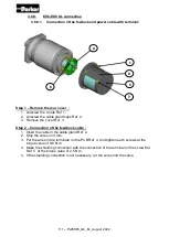
– Connection of the power cable :
1. Insert the cable in the cable gland or conduit stop Ref 2.
2. Strip the wires on 5mm and crimp the wires U, V, W and Ground in the faston
terminals 6,8x0,8.
3. Place the wire U, V, W and Ground on the terminals and plug the wires TH+ and
TH- and also BR+ and BR- in a case of a motor with a brake equiped in the terminal
of the PCB Ref 4 .
4. Crimp the shielding wire in the faston terminal 2,8x0,8 and plug it on the terminal
Ref 5.
5. If the shielding connection is not necessary, cut the wire short the cable.
Step 4
– Fitting of the rear cover :
1. Slowly take up any slack in the cables and close the cover Ref 3.
2. Tighten the cable gland caps or conduits stop Ref 2.
3. Tighten the screws of the connection modules Ref 6 at the torque value of 0,5
N.m.
7.
Place the rear cover Ref 3 and take care to don’t hurt the toric seal placed on the
rear flange.
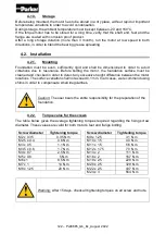
4. Tighten the 4 nuts Ref 1 at the torque value of 5,6 N.m.
5. Connect the outside ground with the screw Ref 7 and tighten it at the torque value
of:
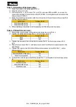
Motor size
Torque value (N.m)
EX3 M4 screw
2,5
EX4 M5 screw
5,6
Summary of Contents for EX Series
Page 1: ...1 Pvd3665_Gb_Ex_August 2022 Servomotors EX Series Technical Manual PVD 3665 EX...
Page 2: ...2 Pvd3665_Gb_Ex_August 2022...
Page 3: ...3 Pvd3665_Gb_Ex_August 2022...
Page 4: ...4 Pvd3665_Gb_Ex_August 2022...
Page 5: ...5 Pvd3665_Gb_Ex_August 2022...
Page 6: ...6 Pvd3665_Gb_Ex_August 2022...
Page 7: ...7 Pvd3665_Gb_Ex_August 2022...
Page 8: ...8 Pvd3665_Gb_Ex_August 2022...
Page 9: ...9 Pvd3665_Gb_Ex_August 2022...
Page 10: ...10 Pvd3665_Gb_Ex_August 2022...
Page 11: ...11 Pvd3665_Gb_Ex_August 2022...
Page 12: ...12 Pvd3665_Gb_Ex_August 2022...
Page 13: ...13 Pvd3665_Gb_Ex_August 2022...
Page 14: ...14 Pvd3665_Gb_Ex_August 2022...
Page 15: ...15 Pvd3665_Gb_Ex_August 2022...
Page 16: ...16 Pvd3665_Gb_Ex_August 2022...
Page 17: ...17 Pvd3665_Gb_Ex_August 2022...
Page 18: ...18 Pvd3665_Gb_Ex_August 2022...
Page 19: ...19 Pvd3665_Gb_Ex_August 2022 Compliance with UL standards...
Page 20: ...20 Pvd3665_Gb_Ex_August 2022 Compliance with UL standards...
Page 73: ...73 Pvd3665_Gb_Ex_August 2022 3 3 Dimension drawings 3 3 1 EX310E...
Page 74: ...74 Pvd3665_Gb_Ex_August 2022 3 3 2 EX420E EX430E...
Page 75: ...75 Pvd3665_Gb_Ex_August 2022 3 3 3 EX620E EX630E...
Page 76: ...76 Pvd3665_Gb_Ex_August 2022 3 3 4 EX820E EX840E EX860E...
Page 77: ...77 Pvd3665_Gb_Ex_August 2022 3 3 5 EX310 C CCC...
Page 78: ...78 Pvd3665_Gb_Ex_August 2022 3 3 6 EX420 C EX430 C CCC...
Page 79: ...79 Pvd3665_Gb_Ex_August 2022 3 3 7 EX620 C EX630 C CCC...
Page 80: ...80 Pvd3665_Gb_Ex_August 2022 3 3 8 EX820 C EX820 C EX820 C CCC...
Page 81: ...81 Pvd3665_Gb_Ex_August 2022 3 3 9 EX310U...
Page 82: ...82 Pvd3665_Gb_Ex_August 2022 3 3 10 EX420U EX430U...
Page 83: ...83 Pvd3665_Gb_Ex_August 2022 3 3 11 EX620U EX630U...
Page 84: ...84 Pvd3665_Gb_Ex_August 2022 3 3 12 EX820U EX840U EX860U...
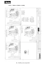
Page 93: ...93 Pvd3665_Gb_Ex_August 2022 3 8 5 Mains supply connection diagrams 3 8 5 1 EX310E...
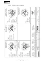
Page 94: ...94 Pvd3665_Gb_Ex_August 2022 3 8 5 2 EX420E EX430E...
Page 95: ...95 Pvd3665_Gb_Ex_August 2022 3 8 5 3 EX620E EX630E...
Page 96: ...96 Pvd3665_Gb_Ex_August 2022 3 8 5 4 EX820E EX840E EX860E...
Page 97: ...97 Pvd3665_Gb_Ex_August 2022 3 8 5 5 EX310 C CCC...
Page 98: ...98 Pvd3665_Gb_Ex_August 2022 3 8 5 6 EX420 C EX430 C CCC...
Page 99: ...99 Pvd3665_Gb_Ex_August 2022 3 8 5 7 EX620 C EX630 C CCC...
Page 100: ...100 Pvd3665_Gb_Ex_August 2022 3 8 5 8 EX820 C EX840 C EX860 C CCC...
Page 101: ...101 Pvd3665_Gb_Ex_August 2022 3 8 5 9 EX310U...
Page 102: ...102 Pvd3665_Gb_Ex_August 2022 3 8 5 10 EX420U EX430U...
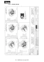
Page 103: ...103 Pvd3665_Gb_Ex_August 2022 3 8 5 11 EX620U EX630U...
Page 104: ...104 Pvd3665_Gb_Ex_August 2022 3 8 5 12 EX820U EX840U EX860U...


