65 – Pvd3675_Gb_Ey_Septembre_2017
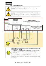
4.3.5. Connection diagrams
Caution: The wiring must comply with the drive commissioning
manual and with recommended cables.
Warning : A bad setting of the electronic control of the close loop
(gain too high, incorrect filtring …) can occur an instability of the shaft
line, vibration, overheating or/and breakdown - . Please consult us
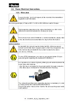
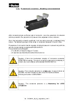
It is mandatory to connect 2 (green-yellow) ground cables between the
motor frame and machine.
•
the first one is connected to the ground pin #2 of power connector,
•
the other one is connected to the external motor housing
(see below).
The connecting of these two grounding devices is mandatory in order
to comply with ATEX standard IEC/EN 60079-0.
The ground cable cross-section must be the same as the power cable
cross-section
BRAKE
(as option)
Supply
: 24 VDC
DC+ DC-
RESOLVER
(as option)
Supply
Signals
∼
∼
SIN
COS
PTC
Thermistor (as a standard)
Thermoswitches (as option)
KTY Sensor (as option)
L1
SERVO DRIVE
L2
MAIN SUPPLY
:
L3
3
∼
AC or 1
∼
AC or = DC
ATEX AREA EY SERVO MOTOR
RESOLVER
MOTOR
Supply
3
∼
PWM
U
V W PE
SERVO DRIVE
main supply connection diagram
Summary of Contents for EY Series
Page 1: ...1 Pvd3675_Gb_Ey_Septembre_2017 Servomotors EY Series Technical Manual PVD 3675 EY Series...
Page 37: ...37 Pvd3675_Gb_Ey_Septembre_2017 3 3 Outline drawings 3 3 1 EY310E...
Page 38: ...38 Pvd3675_Gb_Ey_Septembre_2017 3 3 2 EY420E EY430E...
Page 39: ...39 Pvd3675_Gb_Ey_Septembre_2017 3 3 3 EY620E EY630E...
Page 40: ...40 Pvd3675_Gb_Ey_Septembre_2017 3 3 4 EY820E EY840E EY860E...
Page 44: ...44 Pvd3675_Gb_Ey_Septembre_2017 3 5 2 2 EY420 3 5 2 3 EY430...
Page 45: ...45 Pvd3675_Gb_Ey_Septembre_2017 3 5 2 4 EY620 3 5 2 5 EY630...
Page 46: ...46 Pvd3675_Gb_Ey_Septembre_2017 3 5 2 6 EY820 3 5 2 7 EY840...
Page 47: ...47 Pvd3675_Gb_Ey_Septembre_2017 3 5 2 8 EY860...

