Auto Pilot Soft Start Valve 1/4", 3/8" & 1/2" SSA75 & 3/8", 1/2" & 3/4" SSA105
IS-SSA75/SSA105
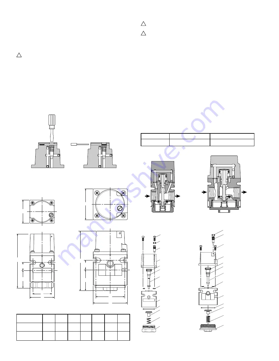
SSA75
SSA105
Figure 3
Dimensions:
SSA75
SSA105
SSA75
SSA105
Figure 1
Adjustment
Figure 2
Lockout Pin Removal
OUT
IN
A
D
F
B
C
E
Cover
Plunger
Assembly
Body
Bottom Spring
Needle Valve &
O-ring
Lockout Pin
Screw
Torque: 2.8 to 4.5 Nm
(25 to 40 in. lb.)
U-Cup*
O-ring*
O-ring* (2)
Gasket*
Disc Holder
Assembly*
Bottom Plug
Torque: 4.5 to 6.8 Nm
(40 to 60 in. lb.)
OUT
IN
A
E
B
D
F
C
Screw
Torque: 2.8 to 4.5 Nm
(25 to 40 in. lb.)
Needle Valve &
O-ring
Lockout Pin
Cover
U-Cup*
O-ring*
O-ring* (2)
Plunger
Assembly
Body
Gasket*
Disc Holder
Assembly*
Bottom Spring
Bottom Plug
Torque: 4.5 to 6.8 Nm
(40 to 60 in. lb.)
Adjustment
The filling speed and pressurization of downstream circuit is
accomplished by a Needle Valve located in the Cover
(See Figure 1). Adjustment is performed using a standard flat
blade screwdriver as indicated in Figure 1. Adjustments can be
made by performing start-up test and adjusting the Needle Valve
from zero to a maximum of 4 turns open until desired equipment
speed is reached.
!
Caution: Do not turn needle valve more than 4 turns out
from closed position as it is a pressure circuit and could
blow out with force.
The adjustment of the initial airflow rate into the downstream side
of the soft-start valve is done with the Needle Valve. Turning Needle
Valve counterclockwise will decrease amount of time to fill
downstream circuit. Turning Needle Valve clockwise will increase
amount of time to fill downstream circuit.
Once the desired start-up speed of the downstream circuit has
been reached, the adjustment area can be blocked off to prevent
tampering by inserting the Lockout Pin provided in the package.
Any further adjustments will require the removal of the Lockout Pin
as shown in Figure 2.
Service
!
Caution: Disconnect or shut off air supply and exhaust
pressure before servicing unit.
!
Caution: Grease packets are supplied with kits for
lubrication of seals. Use only mineral based grease or
oils. Do not use synthetic oils such as esters. Do not use
silicones.
Note:
After servicing unit, turn on air supply and check for leaks.
If leakage occurs, do not operate – conduct repairs and retest.
Note :
Items marked with an * are included in the service kit.
1. Remove the four Screws that retain the Cover and remove Cover.
Next remove Plunger with Seals from Body.
2. Remove Bottom Plug by unscrewing it from the Body. Next
remove Bottom Spring, Disc Holder Assembly and Gasket.
3. Clean, and carefully inspect parts for wear and / or damage.
If replacement is necessary, use parts from service kit.
4. Lubricate O-rings and U-cup with grease (supplied with kit).
5. Install Gasket into Body. Then install Disc Holder, Bottom Spring
and Bottom Plug in to Body. See Figure 3 for torque value.
6. Install Punger with Seals into the Body. Install two O-rings between
Body and Cover (make sure air passages are aligned properly),
install four Screws and tighten per Figure 3.
Service Kits Available:
Description
SSA75
SSA105
Service Kit
RKSS75
RKSS105
There may be extra parts in the kit.
Model
Port
A
B
C
D
E
F
Size
SSA75
3/8"
2.19
4.72
2.06
1.50
1.66
.72
(56)
(120)
(52)
(38)
(42)
(18)
SSA105
1/2"
3.03
5.25
2.75
1.84
2.53
.84
(77)
(133)
(70)
(47)
(64)
(21)
Inches (mm)


