background image

FTIR3 Oil Analyzer

17

Select an equipment profile from the list in the left pane. The “Filter” field can be used to easily sort through 

a long list of equipment names. The information pertaining to the selected Equipment is displayed in the 

right-hand pane, divided into four tabs.

At any time, click on the “Back” arrow to return to the Main Options screen. 

Analysis results for individual interval points can be viewed by clicking on the Equipment name in the 

left-hand pane and selecting the desired interval point (Figure 3-6). If there is any warning or alert in any 

of the sample analyses, it will be highlighted in the left-hand pane. Refer to sections 3.1.2 (c) and 3.1.2 

(d) for further information.

Figure 3-6

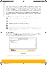
3.1.2 (a) “Details” Tab

The 

Details

 tab (Figure 3-7) displays the Equipment information that was entered in Section 3.1.1, 

as well as the quantitative and spectral results of the Last Sample to be analysed and any applicable 

Messages and Warnings. The icons in the upper portion of the screen allow the user to access various 

functions:

Figure 3-7

MA-K31014-KW FTIR Issue 1.indd   17

14/03/2017   20:16

Summary of Contents for FTIR3

Page 1: ...FTIR3 OIL ANALYZER User Guide MA K31014 KW FTIR Issue 1 indd 1 14 03 2017 20 16 ...

Page 2: ...MA K31014 KW FTIR Issue 1 indd 2 14 03 2017 20 16 ...

Page 3: ...FTIR3 Oil Analyzer 1 FTIR3 Oil Analyzer MA K31014 KW FTIR3 Oil Analyzer MA K31014 KW FTIR Issue 1 indd 1 14 03 2017 20 16 ...

Page 4: ...ation 7 2 Unpacking and Installation 8 2 1 Inspection 8 2 2 Unpacking 8 2 3 Installation 8 2 3 1 Site Requirements 8 2 3 2 Parts of the FTIR3 Oil Analyzer 9 2 3 3 Rear Panel LEDs 10 2 3 4 Sampling Cell 11 2 3 5 Sampling Assembly 12 2 3 6 Setting up the FTIR3 13 2 3 7 Stand by Mode 13 3 Sample Analysis 14 3 1 Equipment Management Screen 15 3 1 1 Creating a new Equipment file 16 3 1 2 Viewing Archiv...

Page 5: ...b 29 4 2 Maintenance and Diagnostic Options 29 4 2 1 Spectrometer Tab 29 4 2 1 a Acquire New Background 29 4 2 1 b Acquire Spectrum 29 4 2 2 User Accounts 30 4 3 Sampling Cell 30 4 4 Desiccant 30 4 5 Software Updates 31 4 6 Laptop Computer 31 4 7 Troubleshooting 32 4 7 1 FTIR3 Helper 32 MA K31014 KW FTIR Issue 1 indd 3 14 03 2017 20 16 ...

Page 6: ...e and the FTIR3 software comes pre loaded with the complete range of JOAP and ASTM approved methods see Section 1 1 2 used for the condition monitoring of in service lubricants 1 1 1 FTIR3 Oil Analyzer Specifications Spectral range 5000 450 cm 1 Resolution 2 cm 1 Interferometer Permanently adjusted Beam diameter 25 mm Beam splitter ZnSe Cell window ZnSe Scanner Mechanical frictionless bearing Freq...

Page 7: ...STM D 7415 09 Trend Analysis of Sulphate By Products by FTIR Spectrometry ASTM D 7624 10 Trend Analysis of Nitration by FTIR Spectrometry Description Notes FTIR3 spectrometer FTIR3 Cleaning fluid 2 x 500 ml bottle FTIR3 laptop Pre installed software and drivers FTIR3 PSU With regional mains cable Laptop PSU With regional mains cable Ethernet cable For connection between FTIR3 and laptop 1 m FTIR3 ...

Page 8: ...d out by qualified service engineers IF DAMAGE IS SUSPECTED disconnect the power otherwise the instrument may become unsafe Some potential indicators The FTIR3 shows visible damage It fails to perform the intended measurement It has been subjected to prolonged storage in ambient conditions that exceed the use and operating parameters It has been subjected to severe transport stresses 1 3 2 Electri...

Page 9: ...ompartment and periodically as a further precaution 3 Do not touch or otherwise contaminate the two IR windows located on the internal sidewalls of the sample compartment If these become dirty the signal level will degrade causing a reduction in the quality of the spectra recorded by the spectrometer If gross contamination is suspected contact Parker Kittiwake for advice 4 Care should be taken to ...

Page 10: ...aging the optics and mirrors 2 2 Unpacking a Move the box to the location where the instrument will be used b Carefully unpack the instrument from the shipping container s Save the packing material for use if the instrument needs to be returned to supplier for service c Visually inspect all equipment d Remove any secondary fasteners shipping tape plastic wraps etc e Notify supplier of any problems...

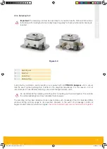
Page 11: ...FTIR3 Oil Analyzer 9 2 3 2 Parts of the FTIR3 Oil Analyzer Figure 2 1 1 Main body 2 Status LED 3 Sampling compartment lid open 4 Sampling cell 4 3 2 1 MA K31014 KW FTIR Issue 1 indd 9 14 03 2017 20 16 ...

Page 12: ...Power jack and retaining clip Use the supplied power cord with mains adaptor K Kensington security slot for optional anti theft lock not supplied 2 3 3 Rear Panel LEDs TKD TaKe Data Green the interferometer mirror is within data acquisition range During data acquisition the light intensity changes to bright green ACC ACCess Yellow the Ethernet connection is communicating with the optics During dat...

Page 13: ...eason it is not recommended to use different sampling cells or interchange between units Do not dismantle the sampling cell without first consulting your Service Engineer This will alter the optical pathlength and may invalidate future analysis The sampling cell has been designed to be robust and as such breakage of the Zinc Selenide ZnSe windows during ordinary usage is not expected However in th...

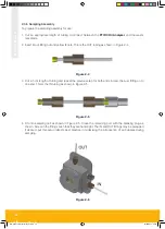
Page 14: ...h of tubing and repeat the previous step for both ends Screw the Luer fitting on to one end This is the IN tubing as shown in Figure 2 5 Figure 2 5 4 Fit onto sampling cell as shown in Figure 2 6 Close the remaining port with the blanking plug as shown Screw in the fittings such that they are hand tight The IN and OUT fittings may be swapped if desired but this setup reflects best practise in mini...

Page 15: ...The status indicator LED light on the top of the FTIR3 Oil Analyzer unit will illuminate A green light indicates the unit is functioning and communicating properly A red light indicates the unit requires a self test or may not be communicating 2 3 7 Stand by Mode The spectrometer can be set into stand by mode by pressing the SBY RES button I located next to the power input Hold the button pressed ...

Page 16: ...eter and the computer are communicating properly If the icon is red then verify the connections to the FTIR3 Oil Analyzer by disconnecting and reconnecting the Ethernet cable If this does not work 1 Ensure the sample compartment is empty 2 Restart the software 3 Disconnect the Ethernet cable reboot the computer and the spectrometer and then reconnect the Ethernet cable If the problem persists plea...

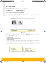
Page 17: ... in the lower right hand corner and then click to confirm 3 1 Equipment Management Screen Clicking the icon from the main screen will open the Equipment Management screen Figure 3 3 where the user can select an existing Equipment Profile or create a new one Figure 3 3 Selecting a saved piece of equipment from the list on the left hand side of the screen will display all the information relating to...

Page 18: ...ect the Oil Type Engine Oil Gear Oil or Transmission Oil from the drop down menu 5 Enter the Oil Name brand grade etc 6 Enter the Interval Units that will be used in for trending hours km etc 7 Once all the information is entered click the Add icon to save the new equipment or click the X icon to exit the dialog without saving the changes 3 1 2 Viewing Archived Analyses The user can view the resul...

Page 19: ... in the left hand pane and selecting the desired interval point Figure 3 6 If there is any warning or alert in any of the sample analyses it will be highlighted in the left hand pane Refer to sections 3 1 2 c and 3 1 2 d for further information Figure 3 6 3 1 2 a Details Tab The Details tab Figure 3 7 displays the Equipment information that was entered in Section 3 1 1 as well as the quantitative ...

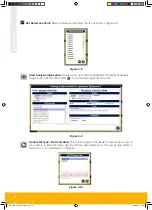
Page 20: ...sults of analysis Figure 3 9 Click the check mark icon in the lower right corner to exit Figure 3 9 Update Oil Type Re trend Data This screen Figure 3 10 allows the user to set a new oil type and to re trend the data collected with the parameters set in the new oil type Refer to Section 4 1 1 for information on Oil Types Figure 3 10 MA K31014 KW FTIR Issue 1 indd 18 14 03 2017 20 16 ...

Page 21: ...for the selected Equipment The Results and Spectra tabs display the results in table format or spectral format respectively Click on the large Print Analysis Report icon to print a report that includes the table of results and the spectral graph as well as any messages or warnings that may be applicable Figure 3 12 For fur ther information on setting the Messages and Warnings please refer to Secti...

Page 22: ...the sampling interval hours km etc Figure 3 13 Click on a parameter from the list on the left hand side to view the graph for that parameter alone To view multiple parameters at the same time hold down the Ctrl key and click on the desired param eters Each selected parameter will be overlaid in a different colour on the spectral graph window MA K31014 KW FTIR Issue 1 indd 20 14 03 2017 20 16 ...

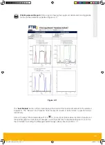
Page 23: ...centage change from the reference or click on Actual to show values in absolute absorbance units Each parameter is listed in its own column Click on any column heading to sort the list by that parameter Use the horizontal scroll bar to view all columns 3 1 2 d Spectra Tab The Spectra tab Figure 3 15 displays the infrared absorbance spectrum of a selected sample or multiple samples by holding Ctrl ...

Page 24: ...s all of the selected sample spectra at the same scale so that spectral data can be accurately compared Full Scale Displays the selected area of the spectra in full scale Reset Scale Resets the spectra window to the default scale Undo Zoom Pan Click this icon to revert to the previously displayed view Save Spectra Click this icon and browse to the desired directory to save the selected spectra fil...

Page 25: ... are required to carry out the analysis of each sample 20 ml Cleaning solution Parker Kittiwake FTIR3 Cleaning Fluid 5 ml Oil sample 1 Syringe for cleaning solution can be reused for the next sample test 1 Syringe for oil sample discard after each sample In addition 20 ml of cleaning solution is recommended to flush the system at the beginning and at the end of each day of testing 10 ml each time ...

Page 26: ... 18 Click the chevron button to initiate the next test sequence Figure 3 18 5 The Analyzing Sample progress screen appears Figure 3 19 indicating that the FTIR3 Oil Analyzer is scanning the sample and collecting a spectrum Figure 3 19 6 Once the oil sample has been analysed use a new clean syringe to flush at least 20 ml of cleaning fluid through the cell Figure 3 20 More cleaning fluid may be use...

Page 27: ...leaning fluid and make it easier to introduce the next sample 8 The Results screen with component results and spectra will appear once the analysis is complete Select the appropriate tab to view either the table of results Results tab Figure 3 22 or spectra Spectra tab Figure 3 23 MA K31014 KW FTIR Issue 1 indd 25 14 03 2017 20 16 ...

Page 28: ...ure 3 23 Alternatively click the icon to print an Analysis Report if desired When finished click on the icon to save the test and return to the Setup screen for additional sample analysis MA K31014 KW FTIR Issue 1 indd 26 14 03 2017 20 16 ...

Page 29: ...es tab Click on the gear icon to access the Oil Types and Parameters Configuration options The FTIR3 software is preconfigured with three types of oil Engine Oil Gear Oil and Transmission Oil Oil types can be added or removed using the controls in the lower left hand corner of the screen below the list of oil types The Details tab Figure 4 2 lets the user enter a name for the new oil type and add ...

Page 30: ...lour flags Figure 4 3 Use the controls in the Messages and Warnings tab to add or remove entries Clicking the icon to add a new message or warning will open a dialog box as shown in Figure 4 4 For each of the oil parameters a value may be set for a low high or ranged cut off such that if the reported value falls outside of this range a notification or custom message will be displayed MA K31014 KW ...

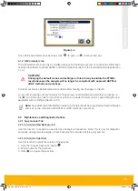
Page 31: ...echniques may create additional parameters by clicking on the icon in the lower left corner which may then be included in future tests by associating the new parameter with an Oil Type Section 4 3 1 Note Any additional Oil Parameters created on this tab cannot be supported by Parker Kittiwake and may not be compliant with ASTM or JOAP methods or practices 4 2 Maintenance and Diagnostic Options 4 2...

Page 32: ... the light and looking through the window The sampling cell may be cleaned by flushing through several times with cleaning fluid as described during the analysis procedure Do not dismantle the sampling cell 4 4 Desiccant The FTIR3 Oil Analyzer is supplied with desiccant sachets which will need to be replaced periodically This may be once a year depending on ambient conditions To replace the desicc...

Page 33: ...ns 4 6 Laptop Computer The FTIR3 Oil Analyzer is supplied with a laptop computer to run the FTIR3 analysis software This computer has been preconfigured to communicate with the spectrometer and no further setup is required Because the FTIR3 Oil Analyzer communicates via Ethernet it is not recommended to make any changes to the TCP IP or proxy settings Parker Kittiwake cannot be held responsible fo...

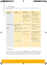
Page 34: ...cle sample analysis will still function correctly Spectrometer software fault Ensure the sampling compartment is empty when starting the software Check all connections Power cycle FTIR3 and or computer Contact your Service Engineer Sampling assembly Results background or sample spectrum abnormal Cell is in the wrong position Verify the cell position and sample loading FTIR3 is leaking Contact your...

Page 35: ...MA K31014 KW FTIR Issue 1 indd 33 14 03 2017 20 17 ...

Page 36: ...W Issue 1 Parker Kittiwake 3 6 Thorgate Road Littlehampton West Sussex BN17 7LU United Kingdom Tel 44 0 1903 731470 Fax 44 0 1903 731480 Email kittiwakeinfo parker com Web www parkerkittiwake com MA K31014 KW FTIR Issue 1 indd 34 14 03 2017 20 17 ...

Reviews: