Parker Hannifin Corporation
Actuator Division
Wadsworth, Ohio USA
73
Catalog AU03-0900P-2/NA
XXX
Maintenance Instructions and Service
HB Series Thrust & Base Slides
Maintenance Instructions & Parts List
Provide Model Number and Serial Number When Ordering Spare Parts.
HB Series
General
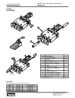
The HB Series products are linear actuators that incorpo-
rate composite or linear recirculating ball bushings and
shaft supports, which provide positive load support and
torque resistance. This manual contains maintenance
instructions, replacement parts information and information
on various options. Consult the factory or product catalog for
additional information.
Specifications:
■
Maximum operating pressure: 150 psi (air)
250 psi (oil) – 2ML cylinder only
750 psi (oil) – 3L cylinder only
■
Operating characteristics: double acting
■
Four support rod sizes: 20, 25, 30 and 35 mm
■
Stroke tolerance: +.030, -.000
■
Mounting: unrestricted
■
Operating temperature range (cylinder):
Standard seals
0 to 165°F
Fluorocarbon seals* 0 to 250°F
■
Filtration requirement: 40 micron filtered, dry air
HBN, HBC, HBT and HBR Thrust Slides
Inspection and Replacement Procedure for Bearings,
Support Shafts and Cylinder:
1. Remove stop collars and bumpers (bumper option).
2. Loosen piston rod locknut and unscrew piston rod from
alignment coupler (HBT, HBR) or tooling plate (HBN,
HBC).
3. Remove tooling plate and support rod assembly from
housing.
4. Remove cylinder bolts and remove cylinder from
housing.
5. Inspect bearings and support shafts. Replace if neces-
sary. (Ball bushings are press fit,composite bushings are
held in place with anaerobic adhesive. Remove bush-
ings from housing only if replacing.)
6. Clean all parts thoroughly.
Reassembly Procedure:
1. Press bearings into housing. Use cylindrical bonding
anaerobic adhesive on composite bushings.
2. Apply a liberal amount of bearing lubricant to ball
bushings. Composite bushings do not require lubrication.
(recommended lubricant is NLG1 grade grease)
3. Replace cylinder and tighten all screws to proper torque
(see table).
4. Screw piston rod into tool plate or alignment coupler and
tighten locknut.
5. Replace bumpers and stop collars if applicable.
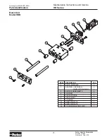
HBB Base Slides
Inspection and Replacement Procedure
for Bearings, Support Shafts and Cylinder:
1. Loosen piston rod locknut and unscrew piston rod from
the housing.
2. Remove cylinder bolts and remove cylinder from
housing.
3. Remove support rod screws and end plates.
4. Remove bumpers and stop collars if applicable.
5. Remove support rods from housing.
6. Inspect bearings and support shafts. Replace if neces-
sary. (Ball bushings are press fit, composite bushings are
held in place with anaerobic adhesive. Remove bush-
ings from housing only if replacing.)
7. Clean all parts thoroughly.
Reassembly Procedure:
1. Press bearings into housing. Use cylindrical bonding
anaerobic adhesive on composite bushings.
2. Apply a liberal amount of bearing lubricant to ball
bushings. Composite bushings do not require lubrication.
(recommended lubricant is NLG1 grade grease)
3. Assemble support rods into housing.
4. Replace bumpers and stop collars if applicable.
5. Assemble end plates and support rods.
6. Replace cylinder and tighten all screws to proper torque
(see table).
7. Screw piston rod into housing and tighten locknut.
TORQUE VALUES (ft-lbs)
HB*15
HB*20
HB*25
CYLINDER HEAD BOLT
5
10
10
SUPPORT ROD BOLT
40
60
90
STOP COLLAR BOLT
5
10
15
SHOCK BLOCK SCREW
5
10
15
SHOCK STOP BOLT
5
10
15
SWITCH BLOCK SCREW
1
1
1
Torque Table
Maintenance Instructions


