20
WWW.PARKERMOTION.COM
PH: (724)
-
861
-
8200
HMR Series Positioners
7.4.2
IP54 Cover Assembly
The cover can be retrofitted; refer to section 11.1.
The following instructions also apply to retrofitting, converting or maintaining the HMR.
For information on necessary disassembly, refer to section 7.4.1.
ATTENTION
It is possible to implement an incorrect assembly sequence.
The cover covers the limit switches on the inside.
Pay attention to the sequence! Make sure you differentiate between:
-
HMR installation
-
Subsequent assembly of the cover and maintenance of the HMR
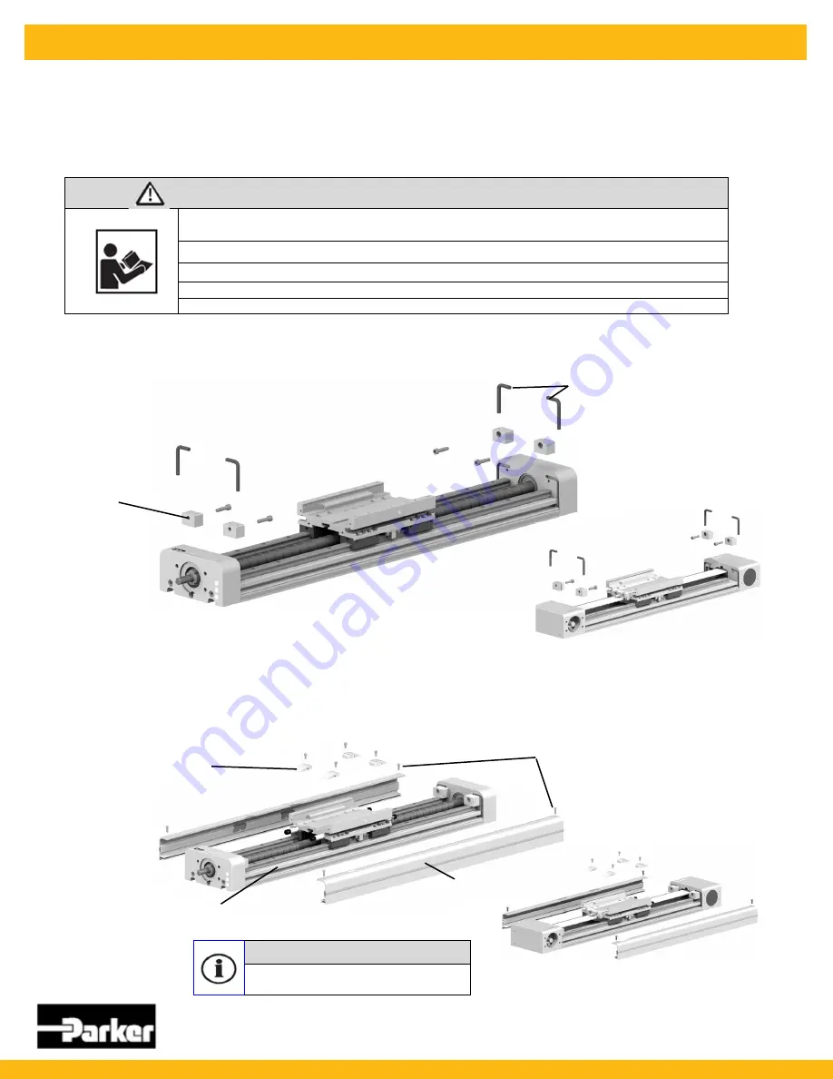
Assemble Hard Stop
•
Insert the
rubber
to seal the covers in the grooves on the cover.
•
Place the
hard stops
on the guide rails 4x and screw these against the cover.
Hard Stop
Rubber
Mount the deflectors and side covers
•
Screw 4x deflectors onto the carriage and grease lightly.
•
Only HMR15, 18, 24: Push the
covers
into the longitudinal grooves on the carrier (clip in) and screw in the four
fastening screws
.
•
Only HMR08, 11: Use
slot nuts
(number corresponding to the stroke length) and screw in the four
fastening screws
.
HMRB
HMRB
Deflector
4x fastening screws
Cover
Only HMR08, 11: Nuts
NOTE
Adhere to the tightening torques for screws
according to section 7.1


