
15
Parker Hannifi n Corporation
Hydraulic Pump/Motor Division
Greeneville, Tennessee USA
Service Manual
HP2 Series Hydrostatic Tandem Pumps
HY13-1521-M1/US
Disassembly
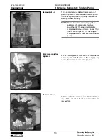
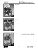
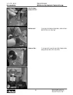
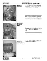
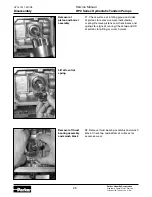
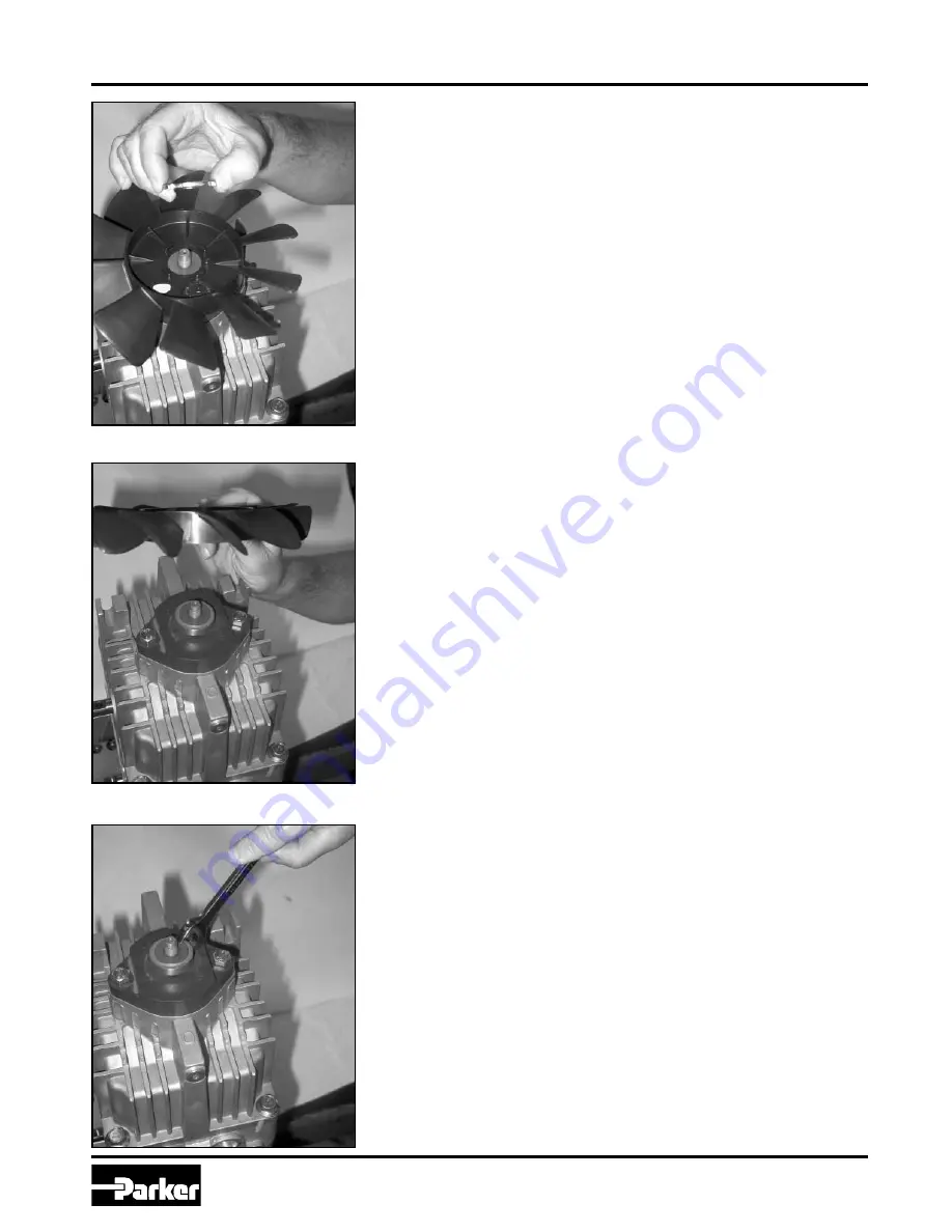
Remove washer
Remove fan
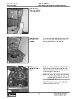
Remove fan
spacer
4. Due to the taper in shaft, use an open end
wrench to pry fan spacer from one side to the
other until loosened, or use a small gear puller.
13
14


