background image

30

Parker Hannifin Corporation

Hydraulic Pump/Motor Division

Greeneville, Tennessee  USA

HY13-1524-002-M1/US

Disassembly & Inspection

Service Manual

HTG Series Integrated Hydrostatic Transmission

HY13-1528-001-M1/US—HTG Series Service Manual

Disassembly and Inspection

Step

Instruction

Illustration

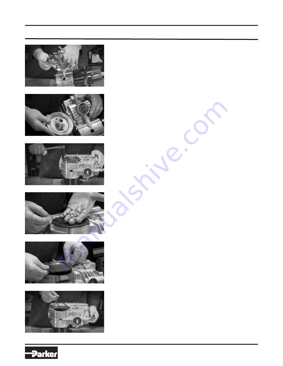
Remove side cover.

2. Replace pulley if damaged or bent

during removal.

1. Loosen the five screws from the side

plate using a ratchet and a 3/8” socket .

Remove pulley.

1. Use an OEM pulley puller or equivalent

standard 2-jaw or 3-jaw puller to remove

the pulley.

2. Remove five side cover screws.

3. Remove the side cover plate.

Remove side cover gasket.

1. The gasket may either still be attached

to the inside of the side cover or sitting

on top of the housing.

2. Inspect gasket for any damage (splits or

tears). Replace if needed.

Summary of Contents for HTG Series

Page 1: ...rated Hydrostatic Transmission Effective August 2021 This product can expose you to chemicals including lead and DEHP which are known to the State of California to cause cancer and birth defects or ot...

Page 2: ...that you analyze all aspects of your application and review the information concerning the product or system in the current product catalog Due to the variety of operating conditions and applications...

Page 3: ...es that a the Service Manual or any explanations illustrations information techniques or tools described herein are either accurate complete or cor rect as applied to a specific Transmission unit or b...

Page 4: ...ntact your local dealer or OEM manufacturer s technical service department Don t try to second guess the Service Manual if problems occur that you cannot solve please con tact your local dealer or OEM...

Page 5: ...ce you have determined that a problem exists start with the easy to check items such as parts damaged from impact that were not properly repaired or that should have been replaced improper replacement...

Page 6: ...spect for cap damage If loose torque to proper torque specifica tion if seal damage replace filter assem bly if cap cracked replace filter assembly X Static seals leaking Side bottom cover Remove cove...

Page 7: ...maintenance equipment Transmissions over heat Check fan for broken blades check for debris wrapped around pulley shaft X NOTE Refer to owners manual for proper transmission fluid and fill volume Engi...

Page 8: ...M Refer to OEM owners manual verify RPM adjust as necessary X Brake Drag Refer to OEM owners manual for proper specified brake adjustment X Loose lug nuts Refer to OEM owners manual for proper torque...

Page 9: ...TG transmissions come factory filled with Parker HT 1000 oil Oil change intervals depend on the type of oil used Follow OEM manufacturers recommended oil change interval Always change the filter when...

Page 10: ...ng the hydraulic system Clean the area around the filler caps before checking oil level Investigate and correct any external leak in the hydraulic system no matter how minor the leak Comply with Parke...

Page 11: ...l Filter 9 6 11 3 115 135 Fan Nut 55 70 Control Arm Bolt 12 5 15 150 180 Brake Assembly 25 28 Castle Nut Patch Lock Nut 200 300 plus rotation to align Cotter Pin Self locking nut for brake drum 200 30...

Page 12: ...sion 12 Parker Hannifin Corporation Hydraulic Pump Motor Division Greeneville Tennessee USA HY13 1524 002 M1 US General Information LH Mower Frame RH Tire Engine Lorem ipsum Tire Transmissions Driver...

Page 13: ...static Transmission 13 Parker Hannifin Corporation Hydraulic Pump Motor Division Greeneville Tennessee USA HY13 1524 002 M1 US General Information UNL REMO A S D INFORMA AND PROP DIVISIO THIRD ANGLE P...

Page 14: ...ROTATING BRACKET 44B 1 420072 ROTATING BRACKET LH 44C 1 420077 RTN ASSEMBLY LH 44D 1 420122 RTN ASSEMBLY LH 44E 1 452028 ROTATING BRACKET 45 1 452011 CONTROL BLOCK 46 1 452020 TRUNNION BLOCK 47A 1 45...

Page 15: ...NUMBER DESCRIPTION 1 4 020207 FLANGE HEAD CAP SCREW 5 16 18 UNC 3A X 0 75 10A 1 025113 NUT 1 20 UNEF 2B 10B 1 025126 NUT 1 20 UNEF 2B 11 1 025164 NUT 5 8 18 UNF 2B 27 1 038016 WOODRUFF KEY 5 16 x 1 2...

Page 16: ...13 1 028025 WASHER FLAT 8 74mm ID X 17 50mm OD X 1 664mm 14 4 028996 WASHER FLAT 406 ID X 827 OD X 098 15 1 100000068 LABEL 19 1 034009 GASKET SIDE COVER FE 20A 1 035007 FITTING BEADED HOSE BARB SAE...

Page 17: ...NG SEAL 18A 1 034008 GASKET BOTTOM COVER FE 18B 1 034007 GASKET BOTTOM COVER COMPOSITE 22A 2 036038 PLUG O RING ASSEMBLY M18 X 1 5 6g 22B 2 409035 PLUG O RING ASSEMBLY M18 X 1 5 6g 23 2 410113 RELIEF...

Page 18: ...16 1 032202 013 PREFORMED O RING SEAL 17 2 032202 116 PREFORMED O RING SEAL 18A 1 034008 GASKET BOTTOM COVER FE 18B 1 034007 GASKET BOTTOM COVER COMPOSITE 19 1 034009 GASKET SIDE COVER FE 20A 1 035007...

Page 19: ...UMBER DESCRIPTION 1 4 020207 FLANGE HEAD CAP SCREW 5 16 18 UNC 3A X 75 10A 1 025113 NUT 1 20 UNEF 2B 10B 1 025126 NUT 1 20 UNEF 2B 11 1 025164 NUT 5 8 18 UNF 2B 27 1 038016 WOODRUFF KEY 5 16 X 1 28 1...

Page 20: ...CKET HEAD CAP SCREW M8 X 1 25 X 25mm 8 15 023002 THREAD FORMING SCREW 1 4 20 X 625 12 1 028022 WASHER FLAT 259 ID X 500 OD X 062 13 1 028025 WASHER FLAT 8 74mm ID X 17 50mm OD X 1 664mm 14 4 028996 WA...

Page 21: ...16 1 032202 013 PREFORMED O RING SEAL 17 2 032202 116 PREFORMED O RING SEAL 18A 1 034008 GASKET BOTTOM COVER FE 18B 1 034007 GASKET BOTTOM COVER COMPOSITE 22A 2 036038 PLUG O RING ASSEMBLY M18 X 1 5 6...

Page 22: ...poration Hydraulic Pump Motor Division Greeneville Tennessee USA HY13 1524 002 M1 US General Information UNLESS OTHERWISE SPECIFIED INTERPRET PER ASME Y14 5M 1994 ANGULAR DIMENSIONS 2 SURFACE ROUGHNES...

Page 23: ...034009 Gasket Side Cover 4 1 SK000277 Sheet 3 Service Bulletin SK000278 HTG SERVICE KIT MOTOR 310cc Right hand Side Item QTY Part Number Description 1 1 TG0310SD081HTAA SA Motor 2 2 032202 116 Packin...

Page 24: ...TY Part Number Description 1 1 040204 Cotter Pin 2 1 490169 Brake Assembly 4 1 490216 Drum Assembly 3 4 020207 Flange Head Screw 4 1 025113 Castle Nut 5 1 SK000284 Sheet 3 Service Bulletin SK000285 HT...

Page 25: ...QTY Part Number Description 1 1 025164 Fan Nut 2 1 477370 Fan Spacer 3 1 420142 Fan 7 8 4 1 SK000345 Sheet 3 Service Bulletin SK000448 HTG HYDRAULIC TRANSMISSION OIL FILTER KIT 2 GAL Item QTY Part Num...

Page 26: ...exploded view illustrations for removal and replacement of the brake assembly and torque specifications Remove the HTG Transmission from the chassis drain it of fluid and take it to a clean work surf...

Page 27: ...lean unit free of grass and other debris Let dry and place on a clean work table 2 Place a pan for oil collection under the unit 1 Remove the cotter pin using needle nose pliers 2 Straighten bent pins...

Page 28: ...mbly and Inspection Step Instruction Illustration Remove brake assembly Remove vent plug 1 Loosen and remove the 4 bolts from the brake assembly using a ratchet and a 5 16 12 pt socket 2 Inspect bolts...

Page 29: ...n Drain oil from unit Remove the fan nut 2 Gently pull out filter by hand 1 With a ratchet and a 15 16 socket loosen and remove the fan pulley nut 2 Use a strap wrench or similar tool to hold the pull...

Page 30: ...de cover 2 Replace pulley if damaged or bent during removal 1 Loosen the five screws from the side plate using a ratchet and a 3 8 socket Remove pulley 1 Use an OEM pulley puller or equivalent standar...

Page 31: ...tegrated Hydrostatic Transmission HY13 1528 001 M1 US HTG Series Service Manual Disassembly and Inspection Step Instruction Illustration Remove four bolts from inside pump 1 Loosen and remove four bol...

Page 32: ...Service Manual Disassembly and Inspection Step Instruction Illustration Remove bottom cover 1 Using ratchet and a 3 8 socket loosen the 10 screws from the bottom cover 2 Remove screws and inspect for...

Page 33: ...r set 1 Inspect inside of charge pump cover for any scoring 2 Replace if necessary 1 Remove both the charge pump rotor and stator 2 May need to use a flathead screwdriver to assist in prying 3 Inspect...

Page 34: ...dblock 2 Remove each cap using a ratchet and a 5 16 hex head socket Remove spring and shock valve from each side Turn endblock to side and remove spring and shock valve Remove rotating group with pist...

Page 35: ...ct port plate for any damage 2 If the brass side of the port plate has heavy scoring replace with a new port plate Remove central spring Remove swash block Remove top washer 0 25 thick Inspect top and...

Page 36: ...vice Manual Disassembly and Inspection Step Instruction Illustration Remove control block The control block should slide off the trunnion shaft However you may need to use a flat head screwdriver to g...

Page 37: ...Tap top of shaft with a rubber mallet to loosen Remove shaft and bearing Remove trunnion arm Once shaft is free from the housing assembly remove the shaft seal 2 Pull pump shaft out of top of pump ho...

Page 38: ...Step Instruction Illustration Disassemble the Motor Remove two 2 end cover O rings Remove three end cover bolts Using a screwdriver or a pick slide the two O rings out from cover grooves Be careful n...

Page 39: ...screwdriver to pry O ring out from the end cover NOTE May need to use a flat head screwdriver to pry section seal from the end cover Remove the commutator It may be necessary to use a flat head screw...

Page 40: ...ustration Remove section seal from both sides of the manifold It may be necessary to use a flat head screwdriver to lift out the two section seals Be careful not to scratch or damage the motor parts R...

Page 41: ...or set Remove section seal from bottom of rotor set 1 Rotate rotor set over 2 Remove the section seal from the bottom of the rotor set Remove the wear plate Remove the thrust bearing from the motor ho...

Page 42: ...ation Remove drive link 1 While motor housing is in vise use hands to gently rotate the drive link out of the shaft Remove the Woodruff key Remove coupling shaft 1 Gently turn the motor housing over 2...

Page 43: ...nspection Step Instruction Illustration Remove the shaft seal 3 Use a screwdriver to pry shaft seal loose from housing groove on the front side of the motor Be careful not to scratch or damage the sea...

Page 44: ...Reassembly of HTG Motor Start with reassembly of the pump section Starting with the top housing clean all parts before reassembly Install trunnion arm seal Seat trunnion arm seal Install trunnion arm...

Page 45: ...g Seat shaft bearing Install pump seal Press seal in place Push shaft and bearing assembly to the bottom of the top housing 3 With the shaft properly aligned to the top housing lightly tap the bearing...

Page 46: ...hing pin hole to pin loca tion in top housing 2 Do not stake pins 3 Apply HT 1000 oil on top of each cradle bushing Install control block onto trunnion arm inside of top housing Install swash block 1...

Page 47: ...lace central spring onto pump shaft 1 Turn assembly onto side while holding pistons in place 2 Slide the assembly rotating slightly over the charge pump shaft 3 Press lightly on rotating group assembl...

Page 48: ...free of debris and Apply HT 1000 oil on the face of end block which will provide some suction and keep the port plate in place during reassembly 2 Place port plate onto endblock with the bronze side f...

Page 49: ...all amount of HT 1000 oil to the face of the bottom face of the endblock Install charge pump Install charge pump cover Install two pump cover bolts and torque 2 Place and align the stator over the rot...

Page 50: ...number one screw torque to 50 60 in lbs 3 Following the number order torque all remaining screws to 50 60 in lbs 1 Place the bottom cover over gasket 2 If installing a standard rubber gasket in sert s...

Page 51: ...st the bearing package 2 The back up ring will lay flat into the groove of housing seal cavity 1 Place motor housing in a soft jawed vice with nose pointed down 2 Using grease provided in seal kit app...

Page 52: ...000 oil to help shaft pass through the lip of shaft seal package 1 Slightly rotate shaft while pushing down so that it passes through the seal pack age and bottoms on top of the thrust washer 2 The to...

Page 53: ...ve link 2 Align wear plate bolt holes to the motor housing bolt holes referencing the V pattern previously drawn on the wear plate Install section seal Install the assembled rotor set Alignment of rot...

Page 54: ...should fit flush with top of rotor Install section seal ring into manifold Install manifold Install section seal Assemble seal and commutator 1 Place manifold over the drive link and onto the rotor s...

Page 55: ...e up Install commutator ring Install section seal in end cover Install end cover O ring Install end cover on top of motor Place commutator ring on top of manifold and align the holes up with the bot h...

Page 56: ...OTE Reference alignment marks on end cover face for correct location 2 Use hand pressure to seat O rings into grooves 2 Tighten with ratchet and a 9 16 socket 3 Torque to 45 55 ft lbs Install top hous...

Page 57: ...on on the endblock where the filter tube hanger is located 2 Insert the other into the second tall loca tion in the endblock 3 Place the shorter endblock bolts into the short endblock hole locations 4...

Page 58: ...over on top of gasket and align the screw holes Install side cover screws Place self tapping screws in all five locations and hand tighten Torque side cover screws Install pulley Install fan Place pul...

Page 59: ...pulling while torquing nut 2 Torque nut to 55 70 ft lbs Fill with HT 1000 oil Replace vent plug Install Woodruff Key Install brake assembly 1 Hand start hollow hex plug 2 Tighten with a 5 16 hex wrenc...

Page 60: ...assembly piloting the Woodruff Key into the matching slot Be careful not to scrape the shaft or dislodge the Woodruff Key while installing the brake drum 2 Torque brake assembly bolts to 25 28 ft lbs...

Page 61: ...61 Parker Hannifin Corporation Hydraulic Pump Motor Division Greeneville Tennessee USA HY13 1524 002 M1 US Notes Service Manual HTG Series Integrated Hydrostatic Transmission...

Page 62: ...e of delivery or when downloaded by a Buyer or end user from the date of the initial download All prices are based upon the exclusive limited warranty stated above and upon the following disclaimer EX...

Page 63: ...its assets 19 Ownership of Software Seller retains ownership of all Software supplied to Buyer hereunder In no event shall Buyer obtain any greater right in and to the Software than a right in the na...

Page 64: ...Parker Hannifin Corporation Hydraulic Pump Motor Division 2745 Snapps Ferry Road Greeneville TN 37745 USA Tel 423 639 8151 www parker com pmd...

Reviews: