background image

IntroDUCtIon

Parker Hannifin icountACM202024

g

6

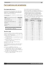
Contamination basics

Solid contaminants in fluid systems vary in size, shape 

and quantity. The most damaging contaminants in fuel 

systems are normally between 6 and 14 microns (and 

therefore invisible to the naked eye). 
The table below gives an indication of the relative sizes of 

common objects.

Object

Typical Size

Grain of table salt

100µm

Diameter of human hair

70µm

Limit of human visibility (naked eye)

40µm

Milled flour

25µm

Red blood cells

8µm

Bacteria

2µm

NOTE: One micron (μm) equals one thousandth 

of a millimetre (1μm = 0.001mm).

the ISo code

The ISO4406 code is the preferred method of reporting 

quantity of contaminants in a fluid. It is comprised of three 

numbers i.e. 

XX / YY / ZZ

, where:


XX

 is the scale number for particles larger than 4µm(c) 

per millilitre of fluid


YY

 is the scale number for particles larger than 6µm(c) 

per millilitre of fluid


ZZ

 is the scale number for particles larger than 

14µm(c) per millilitre of fluid

By definition the three scale numbers will always 

decrease, i.e. XX > YY > ZZ. 
The following table is extracted from ISO4406:1999 and 

defines the range of particles that each scale number 

represents.
For example code 

20/18/13

 indicates that:

  There are between 5,000 and 10,000 particles per 

millilitre larger than 4µm(c) (i.e. scale number 

20

).

  Between 1,300 and 2,500 particles per millilitre larger 

than 6µm(c) (i.e. scale number 

18

).

  Between 40 and 80 particles per millilitre larger than 

14µm(c) (i.e. scale number 

13

).

Fuel cleanliness and contamination

Each increment of scale number represents an 

approximate doubling in the quantity of particles in a 

fluid. In practical tests, results obtained can flick between 

one scale number and the next if the actual number 

of particles counted is close to the crossover point. 

Conversely, results that are one scale number different 

could also indicate nearly four times difference in dirt 

levels (if the actual particle count on one result is close to 

the lower limit of one scale number, and the other result is 

close to the upper limit of the next scale number).

ISO4406 

scale  

number

Number of particles per ml

More than

Up to and 

including

22

20,000

40,000

21

10,000

20,000

20

5,000

10,000

19

2,500

5,000

18

1,300

2,500

17

640

1,300

16

320

640

15

160

320

14

80

160

13

40

80

12

20

40

11

10

20

10

5

10

9

2.5

5

8

1.3

2.5

7

0.64

1.3

Summary of Contents for icountACM202024

Page 1: ...icountACM202024 Aviation Condition Monitoring User Guide P849792 UK REV A Parker Hannifin 2009 www parker com hfde g...

Page 2: ...losure The nameplate attached to the rear of the unit provides the name and address of the manufacturer Parker Hannifin UK Ltd Filter Division Europe Condition Monitoring Centre Brunel Way Thetford No...

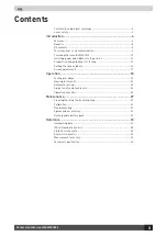
Page 3: ...ting 14 Setting the time and date 16 Screen adjustments 17 Operation 18 Testing procedure 19 Viewing test results 21 Automatic testing 25 Alarm facility and limit levels 26 Operation checklist 28 Main...

Page 4: ...ght methods Particle size ranges 4 6 14 21 25 and 30 microns ISO code range 7 22 Data entry 32 character two line dot matrix LCD Full alphanumeric entry facility on keypad Data retrieval Memory access...

Page 5: ...or service and maintenance personnel Manufactured from lightweight ABS expanded structural foam which is both durable and strong and supplied in an Astraboard carrying case the icountACM202024 is easy...

Page 6: ...is extracted from ISO4406 1999 and defines the range of particles that each scale number represents For example code 20 18 13 indicates that There are between 5 000 and 10 000 particles per millilitr...

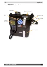
Page 7: ...oduction Parker Hannifin icountACM202024 7 g icountACM202024 front view Printer cover Main Unit On Off switch Limit Switch socket Main Unit Input Hose Battery module Handset see page 9 Main Control va...

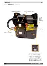
Page 8: ...1 25A fuse and the RS232 connection are located behind the removable cover plate The RS232 interface is provided to download all test data stored in the instrument See the ParSmart Downloader software...

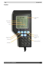
Page 9: ...Introduction Parker Hannifin icountACM202024 9 g Handset Alphanumeric keys Average 3Test feature Paper feed Set display Print result Change mode ISO Code Micron sizes Liquid crystal display Count...

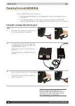
Page 10: ...pack Step 1 Fully loosen the two retained screws and remove the rechargeable battery compartment 2 To charge the unit attach the flying lead of the 12Vdc supply to the input power socket of the recha...

Page 11: ...note of the diagram on the underside of the battery pack This shows which way up the batteries need to be in the pack i e the polarity of the batteries 3 Insert a complete set of fresh batteries in th...

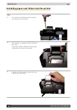
Page 12: ...screw the two retaining screws and remove the printer cover and reel axle 2 Place the new or replacement ribbon cassette in the printer Press down until the cassette is sitting squarely checking that...

Page 13: ...ars through the printer s paper feed slot 5 Place the paper roll in the paper well Check that the metal reel axle is correctly aligned in the slots 6 Feed the paper through the the paper slot in the c...

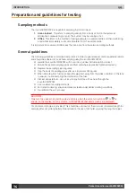
Page 14: ...024 with care it is a precise instrumentation product Ensure hoses and sampling pipes are fitted and where applicable tightened correctly Replace the sampling pipes regularly Cap the ends of sampling...

Page 15: ...ter method available from www energyinstpubs org uk Cleaning sample bottles Bottles used for sampling must be cleaned prior to use This is best done using the fluid to be sampled as follows 1 Fill the...

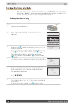
Page 16: ...Press and hold MODE for five seconds RESET DATA Y N is shown on the display To clear all stored test results from the icountACM202024 memory press to move the cursor under Y and press MODE If you do n...

Page 17: ...een adjustments The screen brightness can be adjusted and it has a backlight These are controlled as follows Brightness Press and hold and use to make the screen brighter Press and hold and use to mak...

Page 18: ...o avoid large volumes of air passing through the ACM unit which can give incorrect readings the transfer pump should be primed before use To do this disconnect the hoses to the main unit from P1 P2 on...

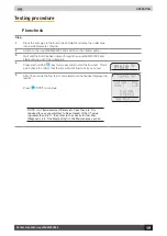
Page 19: ...out of the outlet pipe 4 Press and hold the key for two seconds to start the flow test This is a self check to confirm that there is sufficient flow to carry out a test MANUAL FLOW TEST IN PROGRESS 5...

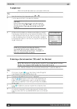
Page 20: ...e icountACM202024 has been calibrated according to ISO11171 1999 Hydraulic Fluid Power Calibration of automatic particle counters for liquids Entering a Serial number ID code for the test NOTE The uni...

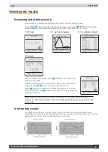
Page 21: ...ve the count and ISO code for each particle size range use the keys to scroll through each screen Press PRINT for a printout of the ISO count results To print all tests to date press the PRINT button...

Page 22: ...Select S to retrieve by Serial number ID code or T to retrieve by Test number Press MODE to confirm 4 Use the alphanumeric keys to enter the Test number or Serial number ID code then press MODE to co...

Page 23: ...tability of results taken from the same fuel sample Note that there must be at least three tests in the icountACM202024 s memory for the 3Test feature to work Step 1 Press 3Test Print to access this p...

Page 24: ...r ID code of the tests to be analysed Press MODE to confirm each entry 5 Press MODE to begin the trend analysis printout Note that graphs print down the page rather than across adjacent points on the...

Page 25: ...e number of tests to be performed range 1 to 300 tests 6 Select Y if a printout of each test is required then press MODE 7 Press to select Y then press MODE 8 Testing starts at the each chosen time Pr...

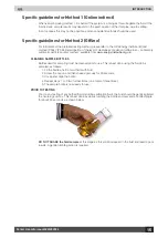
Page 26: ...only and Alarm flashes on the display Any external device connected is also activated If an alarm is sounding after a test then Press and hold and use to silence the alarm Press and hold and use to sn...

Page 27: ...n triggered or not If no the unit runs tests until the level is triggered and then stops Please see the Automatic Testing section for details of set up Limit switch relay manual control To energise th...

Page 28: ...r to analysis there are no dramatic fluctuations in pressure within and between tests trend monitoring is performed under similar working conditions hoses are correctly stowed to avoid fuel spillage i...

Page 29: ...When switching the unit on it will check the date as stored in the real time clock against the date stored as the next calibration due date Parker recommends the icountACM202024 is calibrated annually...

Page 30: ...mulsions Put sample in a clear container and hold up to the light This will show cloudy or clear If cloudy check the type of fuel and change until the fuel is clean Then retry icountACM202024 Diagnost...

Page 31: ...rol of flow through icountACM202024 a Care should be taken to allow fuel to discharge safely and should only be performed by a competent operator Re test and if fault reoccurs return the unit to Parke...

Page 32: ...rgeable battery pack B84817 UK power supply B84830 US power supply B84831 Euro power supply Rechargeable battery pack Type NiMH Nickel Metal Hydride Charging conditions Via supplied charger only Tempe...

Page 33: ...es larger than 4 m c per 100 millilitre of fluid the second number for particles larger than 6 m c per 100 milllilitre of fluid and the third number for particles larger than 14 m c per 100 millilitre...

Page 34: ...202024 g 34 ISO4406 particle distribution chart The chart includes various ISO level contamination grades Number of particles per 100ml greater than indicated size Number of particles per ml greater t...

Page 35: ...amination and Control Research Programme 1980 1984 Ref AHEM Guide to Contamination Control in Hydraulic Power Systems 1985 Solid contaminant code No 15 9 Application Machine tools particle size m Numb...

Page 36: ...nant code No 18 11 Application Mobile systems particle size m Number of particles per 100 ml greater than indicated size Solid contaminant code No 17 12 Application Marine installations Number of part...

Page 37: ...ications Mechanical handling particle size m Number of particles per 100 ml greater than indicated size Solid contaminant code No 16 11 Applications Injection moulding Metalworking Unused commercial g...

Page 38: ...ountACM202024 g 38 Fluid flow schematic A Lift Pump Unit 1 Sample Pipe Inlet 2 Sample Pipe Outlet B Main Unit 3 Monitor block 4 Laser Diode 5 Optical Scanner 6 Main Control Valve 7 Dual Direction Syri...

Page 39: ...ied in ISO procedures thus guaranteeing calibration accuracy Repeatability The icountACM202024 measures and quantifies individual particles using advanced electronics and laser technology to ensure a...

Page 40: ...fuse included for overload protection Return icountACM202024 to Parker Hannifin if the fuse is blown icountACM202024 technology Microprocessor controlled laser optical scanning system Repeatability Ac...

Page 41: ......

Page 42: ...and Dublin Tel 353 0 1 466 6370 parker ireland parker com IN India Mumbai Tel 91 22 6513 7081 85 IT Italy Corsico MI Tel 39 02 45 19 21 parker italy parker com JP Japan Fujisawa Tel 81 4 6635 3050 KR...

Reviews: