background image

IQAN-Lx
Instruction book

Publ no HY33-8330-IB/UK
Edition 2016-02-18

Summary of Contents for IQAN-L Series

Page 1: ...IQAN Lx Instruction book Publ no HY33 8330 IB UK Edition 2016 02 18 ...

Page 2: ...cator showing different Lx modes x 5 Mounting xi Mounting the unit xi Mounting considerations xi Mounting methods xii 6 Installation xiii Connectors C1 and C2 xiii Connector pin assignments xiv Supply Voltage xv Emergency stop xv Connecting of Supply Voltage xv IQAN Lx addressing terminating xvii Addressing xvii Terminating xvii Reference voltage VREF xviii Connecting sensors and switches xix Conn...

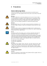
Page 3: ...ections marked with a warning symbol in the left margin indicate that a hazardous situation exists If precautions are not taken this could result in death serious injury or major property damage CAUTION Sections marked with a caution symbol in the left margin indicate that a potentially hazardous situation exists If precautions are not taken this could result in minor injury or property damage NOT...

Page 4: ...ce fields can in extreme cases cause an unintentional change of speed of the output function NOTICE As much as possible of the welding work on the chassis should be done before the installation of the system If welding has to be done afterwards the electrical connections on the system must be disconnected from other equipment The negative cable must always be disconnected from the battery before d...

Page 5: ...ine when first starting up the machine Follow the instructions for function control in the Start up section Safety during maintenance and fault diagnosis CAUTION Ensure that the following requirements are fulfilled before any work is carried out on the hydraulics control electronics The machine cannot start moving Functions are positioned safely The machine is turned off The hydraulic system is re...

Page 6: ... the small lever are the same in terms of signals and therefore both are called IQAN Lx The IQAN Lx module types The control lever s parts Control lever Lx consists of 1 Handle 2 Rocker Option 3 Switch Option 4 Bellows 5 Mounting flange 6 Lower part 7 Connector C1 for CAN bus supply voltage address idTag 8 Connector C2 for inputs and outputs 9 Indicator for supply voltage 10 Status indicator for I...

Page 7: ... expansion unit IQAN XT2 The IQAN Lx can be equipped with a proportional rocker G handle option for LL D handle option for LM or with buttons N or E handle option for LL The following descriptions refer to a fully equipped lever but is also applicable to the functions on levers with no rocker or buttons The IQAN Lx are delivered with an outgoing cable that has 2 connectors for all inputs and outpu...

Page 8: ...is an error message for the system such as a short circuit and input or output interruption By connecting the digital output to a warning lamp or audio signal the driver is alerted that an error message has been given Connection of DOUT Connect the alarm audio signal between pin C2 6 and BAT the battery s negative pole See the illustration below An active output gives battery voltage 11 32 Vdc to ...

Page 9: ...n the display The Lx module will also indicate the error with an error code ref see page 9 Input output Protection All inputs on the Lx module are designed to withstand the maximum specified supply voltage The outputs are protected against short circuit Furthermore an error on one input or the output will not influence other inputs System Diagnostics The yellow blinking LED on the module indicates...

Page 10: ...in the IQAN master to get more information about the Lx module Then following values are measured Status Blink yellow light Normal no errors Error code Error Blink red light 1 I O and voltage errors 2 High temperature 3 CAN error 4 Hardware and VREF error 5 Address error 6 Software error Internal temperature C Power supply V Reference voltage V ...

Page 11: ...posed to external heat e g from the engine or heater Mount the unit so that the LEDs are visible Mount the unit so there is no risk that the harness can be folded crushed worn or damaged in any way Locate the harness so there is no pressure on the connector Use ergonomics The control lever should be mounted at a height so that there is no pressure on the driver s arm and shoulders IQAN LM should b...

Page 12: ... or fastened with a clamp ring NOTICE The clamp ring must be positioned a maximum of 10 mm under the flange Mounting the IQAN LM with a clamp ring Control lever IQAN LL must only be mounted using screws through the flange Mounting the IQAN LL with screws Please refer to the IQAN Lx installation sheet for mounting dimensions max 10 mm 4x ...

Page 13: ...in type AMP no 1062 20 0222 Lock type AMP no 967632 1 Housing C2 AMP no 1 967622 1 C2 Pin type AMP no 2 963745 1 Lock type AMP no 967632 1 Recommended cable 0 75 1 mm2 18 AWG IQAN tool kit Parker no 5031061a a The IQAN tool kit description is found in the IQAN accessories datasheet BAT CAN H CAN L BAT VREF VREF Lx 1x DOUT 2x VIN 6x ext DIN ADDR H ADDR L 4x int DIN ...

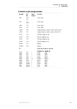
Page 14: ...C1 3 CAN high voltage bus line CAN H C1 12 CAN low voltage bus line CAN L C1 9 CAN high voltage bus line CAN H C1 6 CAN low voltage bus line ADDR L C1 7 Address ADDR H C1 8 Address I O DIN A DIN B DIN C DIN D DIN E DIN F VIN A VIN B DIN G DIN H DIN I DIN J C2 1 C2 2 C2 3 C2 4 C2 5 C2 6 C2 10 C2 11 internal internal internal internal I I I I I I O I I I I I I Alternative functions or naming IQANdev...

Page 15: ...ow to connect the emergency stop Connecting of Supply Voltage The supply voltage should be within the operating range see Appendix A on page xxiii Connect the supply voltage to BAT pin C1 4 through a fuse The fuse shall be 3A fast F The ground connection is made from BAT pin C1 1 to the negative pole on the battery Connecting the emergency stop and voltage supply NOTICE Do not use the chassis as t...

Page 16: ...dule each of the units will have to be separately connected to the battery voltage and protected with a fuse Requisite fuse level should be 3A fast F EXAMPLE Connecting several modules to the power supply Lx A0 Lx A1 Lx A2 LX A3 BAT pos C1 4 BAT pos C1 1 BAT BAT 3 A Symbol for disconnecting switch for battery ignition lock and other fuses ...

Page 17: ... through the CAN bus the CAN bus must be terminated Because the master module always is located at the beginning of the bus the master is provided with an internal termination You will only need to terminate the end of the bus If an IQAN Lx is located at the end of the CAN bus then use an ID tag having a combined address and terminating function This is denoted with a T for terminating after the a...

Page 18: ...y equipped with a voltage regulator to generate the reference voltage VREF The standard reference voltage will feed different kinds of sensors potentiometers and joysticks VREF positions NOTICE Maximum load for the VREF is different according to 12 24 Vdc power supply see Appendix A on page xxiii VREF pos C2 8 VREF pos C2 7 ...

Page 19: ...nnected to the VREF position and the corresponding negative terminal to the VREF position The sensor signal is connected to appropriate VIN position For a resistive type element select the potentiometer value for the sensor to achieve the best linearity NOTICE The negative terminal of the sensor must not be connected to the chassis Maximum load for VREF position see Appendix A on page xxiii EXAMPL...

Page 20: ... xxiii It is possible to connect system voltage BAT to the input through a switch in order to reserve 5Vdc VREF for sensors and potentiometers EXAMPLE Connect the positive and negative terminals of the switch to VREF position C2 8 and DIN A position C2 1 respectively Connecting a switch to DIN A and VREF EXAMPLE Connect the positive and negative terminals of the switch to supply or the unit s BAT ...

Page 21: ...ble s conductor joint Make sure the emergency stop works The emergency stop should disconnect the supply voltage to all modules Alternatively the emergency stop may also shut off the diesel engine or a dump valve and with that depressurize the hydraulic system Prepare for system start WARNING Make sure no one is in dangerous proximity to the vehicle to avoid injuries when it starts Prepare for the...

Page 22: ...assuming that all mentioned preparations have been carried out and have correct values Calibrate and adjust input and output signals according to the instructions related to the master menu system and check each and every output function carefully In addition to these measures the machine shall also meet the machine directives for the country in question ...

Page 23: ...ltage on any pin with respect to BAT 34 V Maximum current into VREF 2 A Maximum current sourced by all outputs 400 mA Environmental ratings Parameter Limit values Unit Remark min typ max EMI EN 55022 1994 conducted emission EN 55022 1994 radiated emission ISO 11452 2 1995 ISO 11452 4 2001 ISO 7637 3 1995 ISO 7637 2 1990 EN 61000 4 8 1993 50 75 80 100 V m mA V V A m class B 0 15 30 MHz class B 30 1...

Page 24: ...tart up delay 300 ms Power to activated output CAN message response time 9 ms Output voltage on VREF 4 9 5 0 5 1 V load 40mA Maximum load current on VREF VBAT 11V to 32V 15 45 48 mA Vdrop 25mV 0 5 Vdrop 50mV 1 Vdrop 100mV 2 Current supply VBAT 14V VBAT 28V 46 57 mA outputs off no load on VREF I O TA 25 C unless otherwise specified Parameter Limit values Unit Remark min typ max VIN Voltage input Si...

Page 25: ... off output Load current 400 mA Voltage drop VBAT VDOUT load IL 0 5A load IL 2A 0 2 0 8 V Off State output current 10 µA Max load inductance 1000 mH 400 mA Short Circuit current limit 1 2 A I O TA 25 C unless otherwise specified Parameter Limit values Unit Remark min typ max ...

Page 26: ...ppropriate context LOW HIGH SUPPLY VOLTAGE VREF ERROR MODULE IS OFFLINE Situation Error code Action Lx Comment BAT 8 5 V Error 1 Check voltage supply BAT 34 V Error 1 Check voltage supply Situation Error code Action Lx Comment VREF 4 9 V Error 1 Check voltage VREF 5 1 V Error 1 Check voltage Situation Error code Action Lx Comment CAN bus off Error 3 All outputs shuts off Check CAN bus ADDR H 4 9 V...

Page 27: ... error Error 4 Contact supplier Situation Error code Action Lx Comment Parameter error Error 6 No calibration of signals Contact supplier Error ZP outer Error 4 No calibration of signals Contact supplier Error ZP inner Error 4 No calibration of signals Contact supplier Error _ axis Error 4 All outputs shuts off Excessive force has been applied to end of stroke Error Start block Error 4 All outputs...

Page 28: ...le types Appendix C Instruction book IQAN Lx Appendix C Dimensioning of the IQAN Lx module types unit mm E2 N0 N2 N2T N4 G U 80 105 105 80 ø6 4x 211 44 218 158 117 ø9 8 ø9 4 8 ø64 ø91 D 50 ø89 45 4x ø5 4x 3 9 5 96 71 69 ø15 A IQAN LM IQAN LL ...

Page 29: ... without notice Parker Hannifin Electronic Controls Division SE 435 35 Mölnlycke Sweden Tel 46 31 750 44 00 Fax 46 31 750 44 21 www parker com ecd Parker Hannifin Electronic Controls Division 1651 N Main Street Morton IL 61550 USA Tel 1 309 266 2200 Fax 1 309 266 6674 Publ no HY33 8330 IB UK Edition 2015 02 18 ...

Reviews: