background image

 12

Addressing/terminating


Instruction book, IQAN

Addressing/terminating

Addressing

Each IQAN expansion module will have a specific address, enabling the master module 
to communicate with the modules through the CAN-bus. When operating, the system 
distinguishes between different modules by first verifying the module type and 
secondly, through the modules having unique addresses.

The maximum number of similar modules in a system is four or eight depending on the 
master module, denoted in the first case as addresses 0, 1, 2, 3 respectively. In order to 
assign any IQAN module a unique CAN-address, an ID-Tag will have to be connected 
to the positions ADDR-H and ADDR-L.

Connecting of Id-Tag.

Terminating

To eliminate interference in the communications through the CAN-bus, the CAN-bus 
must be terminated at both ends. By default, if no ID-tag is installed in an IQAN 
master, it will be terminated internally to be the Bus master and will have no special 
configuration. 
When an IQAN expansion module is located at the end of the CAN-bus, then you 
would use an ID-tag having a combined addressing and terminating function. This is 
denoted with a "T" for terminating, after the appropriate address such as; 0T, 1T, 2T... 
etc. In the application, the same address value as the non-terminated ID-Tag with 
equivalent number will be transferred to the application.

Selecting appropriate ID-Tag

Check the address number of the module assigned in the application.

If the module is located at the end of the CAN-bus, then select the appropriate ID-

Tag denoted with a "T".

N

OTICE

The CAN-bus must not be terminated at the module using an external regular 
terminating resistor, due to the fact that terminating is made from within the module by 
default or in conjunction with the ID-Tag.

EXAMPLE

If having an expansion module with address 0, the system will denote this one as 
[module type]-A0, The letter "A" in the example refers to CAN-bus A. 

ID-Tag

ADDR-L

ADDR-H

IQAN module

Summary of Contents for IQAN-XS2

Page 1: ...IQAN XS2 Instruction book Publ no HY33 8386 IB UK Edition 2015 12 10...

Page 2: ...ck 7 Emergency stop 7 5 Mounting 8 Mounting the module 8 6 Installation 9 Supply voltage 11 Addressing terminating 12 Reference voltage VREF 13 Voltage inputs 14 Digital inputs 17 Digital outputs 19 7...

Page 3: ...s common to the term hazardous situation that a person is exposed to a hazard As a way of pointing out important inform ation for the machine designer that in some way relates to safety This includes...

Page 4: ...ation contains product information in a compact format for details on the information found in those documents consult this manual The IQAN module documentation system Compact Documentation Main Docum...

Page 5: ...ctions on the system must be disconnected from other equipment The negative cable must always be disconnected from the battery before disconnecting the positive cable The ground wire of the welder sha...

Page 6: ...ics may only be carried out by trained personnel who are well acquainted with the control system the machine and its safety regulations Before you start Read section Start up Additional information fo...

Page 7: ...N XS2 module I O overview Inputs The IQAN XS2 module has eight 8 voltage inputs VIN A thru VIN H for connection of 0 5 Vdc signals The inputs may be configured as digital inputs DIN A thru DIN H Volta...

Page 8: ...n Off outputs The XS2 module has six 6 on off outputs that are high side power outputs CAN related functions The master uses the CAN bus CAN Controller Area Network to communicate with the modules The...

Page 9: ...r an application defined error value for the module inputs and the module outputs will be off The error will be presented on the master display module if there is one and with a related blink code on...

Page 10: ...red to the module Locate the module to protect it fro m high pressure washing or similar Locate the module so that the cab le connector is facing down Locate the module so th at the LEDs are visible N...

Page 11: ...raction tool IQAN tool kit Parker no 5031061 Logical Symbol Pin No I nput or O utput Function description and or Signal name s BAT 28 Power supply positive BAT 15 Power supply negative ground VREF 42...

Page 12: ...DIN D VIN E DIN E VIN F DIN F VIN G DIN G VIN H DIN H Note DIN A to DIN H have high impedance inputs 62K Ohm P1 P1 0 P1 1 P1 2 P1 3 P1 4 P1 5 8 9 22 23 36 37 O O O O O O P1 is an 6 pin output port DO...

Page 13: ...r should be as close to the battery as possible for safety IQAN expansion modules do not have RTC WARNING Risk of injury To reduce the risk for uncontrolled supply of an IQAN master module i e a short...

Page 14: ...it will be terminated internally to be the Bus master and will have no special configuration When an IQAN expansion module is located at the end of the CAN bus then you would use an ID tag having a co...

Page 15: ...ors and potentiometers VREF positions NOTICE It is strongly recommended to use the module s VREF and VREF to all sensors and potentiometers that are connected to the module inputs This will reduce bad...

Page 16: ...on NOTICE The negative terminal of the sensor must not be connected to the chassis Maximum load for VREF position see Appendix A Connecting other 3 wire sensors The same type of connection shown for p...

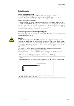
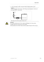
Page 17: ...d be connected to VREF and VIN DIN respectively for 5V signal The current consumption for the input is negligible NOTICE Maximum load for VREF position see Appendix A EXAMPLE Connect the negative term...

Page 18: ...ed to connect system voltage BAT to the input through a switch in order to reserve 5Vdc VREF for sensors and potentiometers EXAMPLE Connect the positive and negative terminals of the switch to supply...

Page 19: ...ing switches to the digital inputs DIN that share pins with CRET extra precautions should be taken WARNING The DIN that share pins with the CRET positions of the proportional outputs have a possibilit...

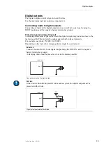
Page 20: ...4 Vdc systems The DIN signal will not be detected by the module Remember that these flexible I O pins must be configured in pairs of the same type EXAMPLE Connect the supply of the switch to BAT throu...

Page 21: ...ut and ground as close to the load as possible This protects the output against high voltage transients For example use diode 1N5408 3A 1000V Depending on the load other clamping diodes might be used...

Page 22: ...a tively the emergency stop may also shut off the diesel engine or a dump valve and with that depressurize the hydraulic system Prepare for system start WARNING Make sure no one is in dangerous proxim...

Page 23: ...dicate error status through the red blinking LED This gives an immediate diagnosis as to the nature of the error that has occurred The location of the LED indicators on the IQAN module The green LED i...
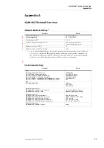
Page 24: ...vironmental ratings Parameter Remark EMI ISO 14982 1998 Radiated emission EN 55025 2003 Conducted emission ISO 11452 2 1995 Radiated Susceptilbility ISO 11452 4 2001 Conducted Susceptibility ISO 7637...

Page 25: ...erature drift 25 mV C Maximum load current 150 mA Protection overload SCB SCG Diagnostics under over voltage Under over voltage threshold 250 mV from nominal value I O TA 25 C unless otherwise specifi...

Page 26: ...T A to DOUT F 1 0 mA DOUT G to DOUT L Max load inductance 200 mH 1 5 A load 500 mH 1 A load Short Circuit current limit 6 A Protection overload SCB SCG Diagnostics no CAN TA 40 C to 70 C unless otherw...

Page 27: ...XS2 module WARNING Don t use the machine if an error message or error code is activated The following sections will present what measures to take for different error situations put into appropriate co...

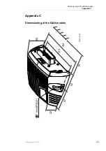
Page 28: ...26 Dimensioning of the IQAN module Appendix C Instruction book IQAN Appendix C Dimensioning of the IQAN module 7 mm M6 x2 142 164 60 32 67 52 75 Unit mm...

Page 29: ...All output turned off 7 CAN L to CAN H No CAN communication All output turned off 8 CAN termination failure termination on No effect 9 CAN termination failure termination off Dependent on CAN size an...

Page 30: ...ssage Turning outputs off is controlled by CAN master unit and therefore delayed maximum 2 bus cycles 2 VIN Short circuited to BAT VIN out of range will create a VIN error VIN Predefined error valuea...

Page 31: ...e without notice Parker Hannifin Electronic Controls Division SE 435 35 M lnlycke Sweden Tel 46 31 750 44 00 Fax 46 31 750 44 21 www parker com Parker Hannifin Electronic Controls Division 1651 N Main...

Reviews: