background image

MX80L Series Product Manual  


Chapter 2 – MX80L Series Table Specifications 


Parker Hannifin Corporation 

Daedal Division 
Irwin, Pennsylvania

19 

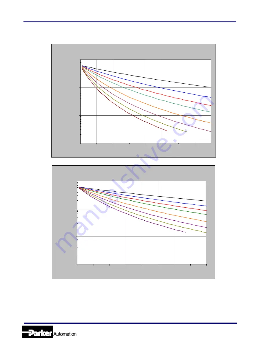
[T03] Travel Moment Life – Load Charts 


Life- Moment Chart 100mm travel Pitch-Yaw Loading

25

50

75

100

150

200

250

300

100

1000

10000

100000

0

1

2

3

4

5

6

7

8

Load [kg]

L

ife

 [k

m]


Life - Moment Chart 100mm travel Roll Loading

25

50

75

100

150

200
250

300

100

1000

10000

100000

0

1

2

3

4

5

6

7

8

Load [kg]

L

ife

 [k

m]


www.comoso.com

Summary of Contents for MX80L series

Page 1: ...Manual No 100 5326 01 Rev 8 MX80L Precision Grade MX80L Standard Grade Product Manual Effective July 11 2011 Supersedes March 1 201 Electromechanical Positioning Systems Daedal www comoso com ...

Page 2: ...IMPROPER SELECTION OR IMPROPER USE OF THE PRODUCTS AND OR SYSTEMS DESCRIBED HEREIN OR RELATED ITEMS CAN CAUSE DEATH PERSONAL INJURY AND PROPERTY DAMAGE This document and other information from Parker Hannifin Corporation its subsidiaries and authorized distributors provide product and or systems options for further investigation by users having technical expertise It is important that you analyze ...

Page 3: ...S TECHNICAL DATA 22 BLANK PAGE 23 ELECTRICAL SPECIFICATIONS 24 CLEAN ROOM PREPARATION 25 ENCODER SPECIFICATIONS 26 HALL EFFECT SPECIFICATION 26 LIMIT AND HOME SENSOR SPECIFICATIONS 26 LOW ESD SPECIFICATIONS 26 DRIVE SPECIFICATIONS 26 STANDARD CABLING AND WIRING DIAGRAMS 27 COMPAX3 CABLING AND WIRING DIAGRAMS 28 CHAPTER 3 HOW TO USE THE MX80L 29 MOUNTING ORIENTATIONS 29 MOUNTING SURFACE REQUIREMENT...

Page 4: ...poration Daedal Division Irwin Pennsylvania 4 CROSS ROLLER BEARING LUBRICATION 40 APPENDIX A INTERNAL PROTECTION 41 NOTE NUMBER INDICATORS ABOVE REPRESENT ONLY A PARTIAL LIST OF IP RATING SPECIFICATIONS 41 APPENDIX B EC DECLARATION OF CONFORMITY 42 INDEX 43 www comoso com ...

Page 5: ...mits Home Revision 5 Added information for the T05 200mm travel positioner Revision 6 Updated electrical specification for the resistance and inductance on D11 and D13 motors page 23 Added the following Note to page 26 Tables purchased before June 1 2009 require an interpolator box and a bypass cable for 10 and 20 nanometer resolutions Revised Static Friction for D11 motor from 0 5N to 1 0N page 2...

Page 6: ...ioner from the shipping container and inspect the unit for any evidence of shipping damage Report any damage immediately to your local authorized distributor Please save the shipping container for damage inspection or future transportation Incorrect handling of the positioner may adversely affect the performance of the unit in its application Please observe the following guidelines for handling an...

Page 7: ...ay approach 125 C The unit itself may become warm or hot to the touch Electrical Shock DO NOT take apart or touch any internal components of the positioner while unit is plugged into an electrical outlet SHUT OFF power before replacing components to avoid electrical shock High Magnetic Field Unit may be HAZARDOUS to people with Pace Makers or any other magnetically sensitive medical devices Unit m...

Page 8: ...s C Specifications Are Mounting Surface Dependent Catalog specifications are obtained and measured when the positioner is fully supported bolted down and is mounted to a work surface that has a maximum flatness error of Standard Grade 0 003mm 300mm 0 0001 ft Precision Grade 0 001mm 300mm 0 00004 ft Table will operate with work surface 0 100mm 300mm but performance specifications will be significan...

Page 9: ...ion Parker Hannifin Corporation Daedal Division Irwin Pennsylvania 9 Assembly Diagram CARRIAGE Anti Cage Creep Cross Roller Bearings Limit Flag Bracket Left side of stage w r t cables X Travel BASE Linear Motor Coils Encoder Read Head www comoso com ...

Page 10: ...es Product Manual Chapter 2 MX80L Series Table Specifications Parker Hannifin Corporation Daedal Division Irwin Pennsylvania 10 Chapter 2 MX80L Series Table Specifications Order Number Nomenclature www comoso com ...

Page 11: ...MX80L Series Product Manual Chapter 2 MX80L Series Table Specifications Parker Hannifin Corporation Daedal Division Irwin Pennsylvania 11 Dimensional Drawings www comoso com ...

Page 12: ...ravel 25 and 50mm travel 45 0 1 77 Z AXIS SHOWN AT MID TRAVEL POSITION 13 1 0 51 P N 100 9822 01 QTY 2 P N 002 2223 01 CYLINDER ASSY MX80L T01 OR T02 16 0 0 63 5 6 0 22 125 0 4 92 100mm travel 2 1 0 08 220 0 8 66 MX80L T03 002 2223 02 CYLINDER ASSY 5 6 0 22 16 0 0 63 002 2223 02 Cylinder Ass y 5 6 0 22 MX80L T03 16 0 0 63 50 0 1 97 Z Axis shown at Mid travel 2 1 0 08 P N 100 9822 02 Qty 2 www como...

Page 13: ...es Table Specifications Parker Hannifin Corporation Daedal Division Irwin Pennsylvania 13 150mm travel 75 0 2 95 Z Axis at Mid travel 7 1 0 28 285 0 11 22 P N 100 9822 02 QTY 2 MX80L T04 P N 002 2223 03 CYLINDER ASSY 16 0 0 63 5 7 0 22 www comoso com ...

Page 14: ...MX80L Series Product Manual Chapter 2 MX80L Series Table Specifications Parker Hannifin Corporation Daedal Division Irwin Pennsylvania 14 General Table Specifications www comoso com ...

Page 15: ...or measured by a laser interferometer and prism located at 38mm above the center of the table This type of measurement sums the X Y Z roll pitch and yaw errors Temperature deviations from test condition may cause deviations in straightness flatness accuracy and repeatability from catalog specifications Tests are performed with the table mounted to a granite table unloaded at 20o C In this example ...

Page 16: ...o include the weight of all positioning elements that contribute to the load supported by the primary axis The life load charts are used to establish the table life relative to the applied loads Life Load Curve All Travels Moment Load Life Curves The effect of moment loading on the bearing life is dependent upon load and lever arm The lever arm in this case is measured from the center of the surfa...

Page 17: ...nnsylvania 17 T01 Travel Moment Life Load Charts Life Moment Chart 25mm travel Pitch Yaw Loading 25 50 75 100 1 50 200 250 300 100 1000 10000 100000 0 1 2 3 4 5 6 7 8 Load kg Life km Life Moment Chart 25mm travel Roll Loading 25 50 75 100 150 200 250 300 100 1000 10000 100000 0 1 2 3 4 5 6 7 8 Load kg Life km www comoso com ...

Page 18: ...ennsylvania 18 T02 Travel Moment Life Load Charts Life Moment Chart 50mm travel Pitch Yaw Loading 25 50 75 100 150 200 250 300 100 1000 10000 100000 0 1 2 3 4 5 6 7 8 Load kg Life km Life Moment Chart 50mm travel Roll Loading 25 50 75 100 150 200 250 300 100 1000 10000 100000 0 1 2 3 4 5 6 7 8 Load kg Life km www comoso com ...

Page 19: ...nnsylvania 19 T03 Travel Moment Life Load Charts Life Moment Chart 100mm travel Pitch Yaw Loading 25 50 75 100 150 200 250 300 100 1000 10000 100000 0 1 2 3 4 5 6 7 8 Load kg Life km Life Moment Chart 100mm travel Roll Loading 25 50 75 100 150 200 250 300 100 1000 10000 100000 0 1 2 3 4 5 6 7 8 Load kg Life km www comoso com ...

Page 20: ...nnsylvania 20 T04 Travel Moment Life Load Charts Life Moment Chart 150mm travel Pitch Yaw Loading 25 50 75 100 150 200 250 300 100 1000 10000 100000 0 1 2 3 4 5 6 7 8 Load kg Life km Life Moment Chart 150mm travel Roll Loading 25 50 75 100 150 200 250 300 100 1000 10000 100000 0 1 2 3 4 5 6 7 8 Load kg Life km www comoso com ...

Page 21: ...tual lever arm Example Given a MX80L T02 with a 2 kg load mounted 35 mm off of the end of the carriage in line with the travel path The lever arm is 35 mm 40 mm center of table to edge 75 mm This loading produces a pitch moment Therefore using the Pitch curve for the 50mm travel draw a vertical line up from the x axis at the 2 kg load point until it intersects the 75 curve The point of intersect i...

Page 22: ...X80L are shown for all available travels In the maximum allowable travel range the motor force is the same for 80 and 48 VDC bus voltage See Electrical Specifications for motor parameters Performance based on table mounted to 200mmx150mmx20mm Aluminum plate Curves shown include friction and viscous damping values of table Peak speed is limited by travel length for 25mm T01 and 50mm T02 travel leng...

Page 23: ...MX80L Series Product Manual Chapter 2 MX80L Series Table Specifications Parker Hannifin Corporation Daedal Division Irwin Pennsylvania 23 Blank Page www comoso com ...

Page 24: ...6 Viscous Damping B N m s 0 500 0 5 0 800 Static Friction 13 Fs N 1 0 1 0 1 0 Motor Thermal Time Constant Tau_th minutes 0 8 0 8 0 8 Winding Thermal Time Const Tau_wnd minutes 0 5 0 5 0 5 Intermittent Force Duration 10 T_2x seconds 8 0 10 0 10 0 Peak Force Duration 11 T_3x seconds 1 2 2 3 2 3 Electrical Pitch 12 Pe mm 13 13 13 Rated Winding Temperature RT C 95 95 95 Rated Ambient Temperature AT C ...

Page 25: ...ge mounting surface with a particle counter capable of measuring 0 3 μm diameter and larger particles Based on results from testing following the 209E Federal Standard the following chart shows the expected clean room compatibility of the MX80L with Class 10 clean room prep Consult factory for details on test methodology and results Compatibility is defined as not affecting the clean room class ra...

Page 26: ...tion 0 06 meters sec 10 nanometer resolution 0 03 meters sec Hall Effect Specification Description Specifications Input Power 5 VDC 30 mA Output Open collector Current Sinking 20 mA Max Limit and Home Sensor Specifications Description Specification Input Power 5 VDC 60 mA power from encoder no additional connection needed Output Output form is selectable with product Normally Closed Current Sinkin...

Page 27: ...ter resolutions ViX X5 LIMITS CONNECTOR PIN FUNCTION WIRE COLOR 1 GND BLACK 6 End of travel ORANGE 7 End of travel BLUE 8 Home GREEN ViX X1 MOTOR LEADS WIRE COLOR DRIVE RED U WHITE V BLACK W GREEN GND ViX X2 FEEDBACK HALL CONNECTOR PIN FUNCTION WIRE COLOR 1 Encoder Z ORANGE 2 Encoder Z BROWN 3 GND BLACK WHITE GREEN 5 5V RED WHITE GREEN 6 Temperature YELLOW BLACK 7 Encoder A WHITE 8 Encoder A YELLO...

Page 28: ...ACK Compax3 X13 FEEDBACK HALL CONNECTOR PIN FUNCTION WIRE COLOR 1 Sense WHITE GREEN 2 Sense WHITE BLUE 3 Hall 1 WHITE BROWN 4 5V Encoder Hall RED 5 5V 2 2K Ohm to T Pin10 6 Hall 2 WHITE ORANGE 7 A V1 YELLOW 8 A V1 WHITE 9 Hall 3 WHITE VIOLET 10 T YELLOW RED 11 B V2 BLUE 12 B V2 GREEN 13 Z V0 ORANGE 14 Z V0 BROWN 15 GND T BLACK YELLOW BLACK Compax3 X3 MOTOR LEADS WIRE COLOR DRIVE RED U WHITE V BLAC...

Page 29: ...ositioner must be bolted down using all counter bored mounting holes provided 4 on T01 T02 8 on T03 T04 T05 using M4 socket head cap screws 70 0 2 76 CENTERED E E 70 0 2 76 CENTERED 50 0 1 97 CENTERED 25 0 0 98 CENTERED C BORED HOLES ON BASE FOR M4 X 0 7 X 8 0 LENGTH SOCKET CAP HEAD SCREW Ø4 008 0 012 0 000 Ø0 1578 0 0005 0 0000 DOWEL PIN HOLES QTY 2 BASE The positioner must be mounted to a flat s...

Page 30: ...ortion of the table Additionally in X Y Systems the overhung portion of the Y axis may not met specifications due to the additional error caused by deflection and non support of the base Contact Daedal for guidelines on specifications of overhang applications Load Mounting Requirements Dowel holes are included in the carriage of the MX80L for repeatable mounting of loads fixturing When bolting pay...

Page 31: ...d circuit board in the base If the magnetic sensor limit and home are desired the unit must be returned to the factory on an RMA To change Limit Home operation from Normally Open to Normally Closed or from Normally Closed to Normally Open a new limit flag bracket must be purchased contact factory for proper configuration and part number To adjust the operating position of the limits limit home adj...

Page 32: ...rs sec2 Using the supplied limit flag sheet cut two 5 0mm long strips from the appropriate white or black depending on configuration marked Limit Home Adjustment overlay decal and follow the procedure for changing the limits Adjusting the Limit Flag Procedure The following procedure is to be used for changing the limit flag switching activation from N O to N C or vice versa and adjusting the activ...

Page 33: ...nd the target is located between the limit targets The sensor is typically used in conjunction with the encoder Z marker If another home location is desired the home target can be adjusted by removing the limit flag decal and applying adjustment overlay decals in the desired location Z Channel Position Reference The Z channel is an output on the encoder Many servo controllers support this input Th...

Page 34: ...ive from Parker The motor cable is terminated with flying leads which are stripped and tinned and ready for installation into the screw terminals on the ViX drive For wire color codes and pin outs see tables in electrical section of manual The limit home cable is optional and therefore if not ordered a space will be open in the clamp at the connection point The limit home cable is provided with a ...

Page 35: ...ccessory kit is strongly recommended The pneumatic accessory kit includes a filter regulator precision regulator fittings and 1 8 ID tubing The pressure in the pneumatic cylinder can be set to provide a balancing force to counter act the effect of gravity The counter balance force FC is a linear function of the pressure P and the cylinder piston area AC FC PxAC See the following table to set the c...

Page 36: ...g the settling time Speed Limits The Maximum Speed of the MX80L is limited by three 3 factors Travel Length The short travel length of the MX80L is the main limiting factor for maximum speed The T01 and T02 options 25mm and 50mm a triangular motion profile with 5g accel decel will only yield peak speeds of 1 1m sec and 1 5 m s respectively Linear Encoder Limit The linear encoder has speed limits r...

Page 37: ...ample A standard grade MX80L with 150mm travel is being used The accuracy over the entire travel is 25 microns 20 C If the carriage temperature increases by 5 C an additional error of 17 microns will be added over the total travel 0 000022mm mm C 150mm 5 C However this additional error can be compensated for since the error is linear The accuracy of the MX80L is plotted with respect to carriage te...

Page 38: ...ects must either be removed by regulating carriage temperature or compensated for with a correction factor added to the commanded position Controlling the carriage temperature is the best method However this means controlling the ambient temperature by removing all heat cold generators from the area and operating at very low duty cycles Compensation is the other way of achieving accuracy without s...

Page 39: ...me use 3 of the 5 inputs A VM15 PF screw terminal breakout board may be purchased to allow access to the remaining 2 inputs and all of the outputs X2 FEEDBACK HALL CONNECTOR PIN FUNCTION WIRE COLOR 1 Encoder Z ORANGE 2 Encoder Z BROWN 3 GND BLACK 5 5V RED 6 Temperature YELLOW BLACK 7 Encoder A WHITE 8 Encoder A YELLOW 9 Hall 1 WHITE BROWN 10 Temperature YELLOW RED 11 Encoder B BLUE 12 Encoder B GR...

Page 40: ...rticularly the limit side bearing can cause unit to malfunction Excess oil can damage limit sensor and target Clean Room Prep Recommended Lubricant Castrol Braycote 803 grease Lubrication Interval 2000 hours Method Lightly coat the bearing surfaces with grease Bearings surfaces can be exposed by moving the table to the end of travel lubricating the now exposed surfaces then moving the table to the...

Page 41: ...ction provided against access to hazardous parts against ingress of solid foreign objects and against the ingress of water First Number The first number indicates protection of persons against access to dangerous parts and protection of internal equipment against the ingress of solid foreign objects 1 Protection against access to hazardous parts with the back of a hand and protected against solid ...

Page 42: ...MX80L Series Product Manual Appendix Parker Hannifin Corporation Daedal Division Irwin Pennsylvania 42 Appendix B EC Declaration of Conformity www comoso com ...

Page 43: ...33 Specifications 26 ViX 39 Horizontal Translation 21 Ingress Protection Rating 41 Internal Protection 41 42 Limit Sensor Adjusting 32 Specifications 26 ViX 39 Lubrication 40 Maintenance 40 Mass 14 Motor Force 36 Motor Heating 38 Mounting 29 Surface Requirements 29 30 Overhang 30 Repair Information 7 Repeatability 33 Specifications 14 Thermal Effects 37 Return Information 7 Settling Time 36 Shield...

Reviews: