MX80L Series Product Manual
Chapter 3 - How to Use the MX80
Parker Hannifin Corporation
Daedal Division
Irwin, Pennsylvania
29
Chapter 3 - How to Use the MX80L
Mounting Orientations
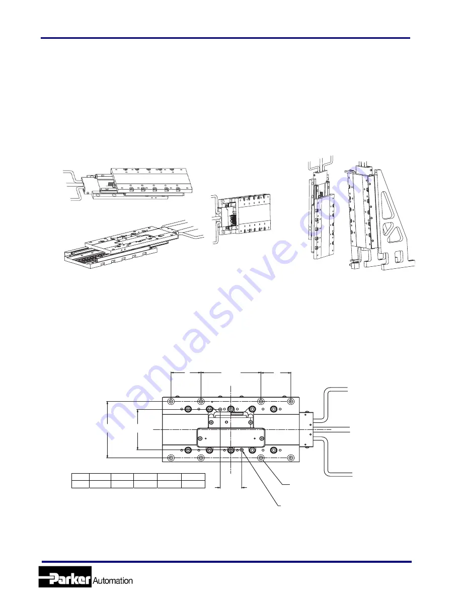
The MX80L can be mounted normal, inverted, side or vertically. For vertical (z-axis) mounting the
pneumatic counter balance is recommended to compensate for the effect of gravity on the carriage and
the load. For all mounting orientations, the cables should be secured as to not interfere with the movement
of the carriage and bearings.
.
Mounting Surface Requirements
Proper mounting of the MX80L is essential to optimize product performance. All specifications are based
on the following conditions:
•
The positioner must be bolted down using all counter bored mounting holes provided (4 on T01 &
T02, 8 on T03, T04, & T05) using M4 socket head cap screws.
70.0 [2.76]
CENTERED
"E
"E"
70.0 [2.76]
CENTERED
50.0 [1.97]
CENTERED
25.0 [0.98]
CENTERED
C-BORED HOLES ON BASE
FOR M4 X 0.7 X 8.0 LENGTH SOCKET CAP HEAD SCREW
Ø4.008
+0.012-0.000
[
Ø0.1578
+0.0005-0.
0000
]
DOWEL PIN HOLES QTY.(2)
BASE
•
The positioner must be mounted to a flat, stable surface, with a flatness error less than or equal to
0.025mm/300mm for operation (specifications will be greatly varied from published specification).
To meet catalog specifications the surface must have a flatness error less than or equal to
0.003mm/300mm for Standard grade and 0.001mm/300mm for Precision grade.
INVERTED
SIDE MOUNTED
HORIZONTAL
P/N 100-9822-02 QTY.(2)
With c’balance and z-bracket
VERTICAL
T01 T02 T03 T04 T05
‘E’ n/a n/a 35.0 65.0 50.0
BASE
www.comoso.com


