background image

K3.1.114o Manual NitroFlow Mobile 


- 9 - 

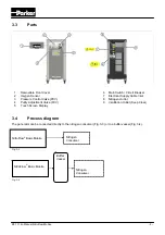
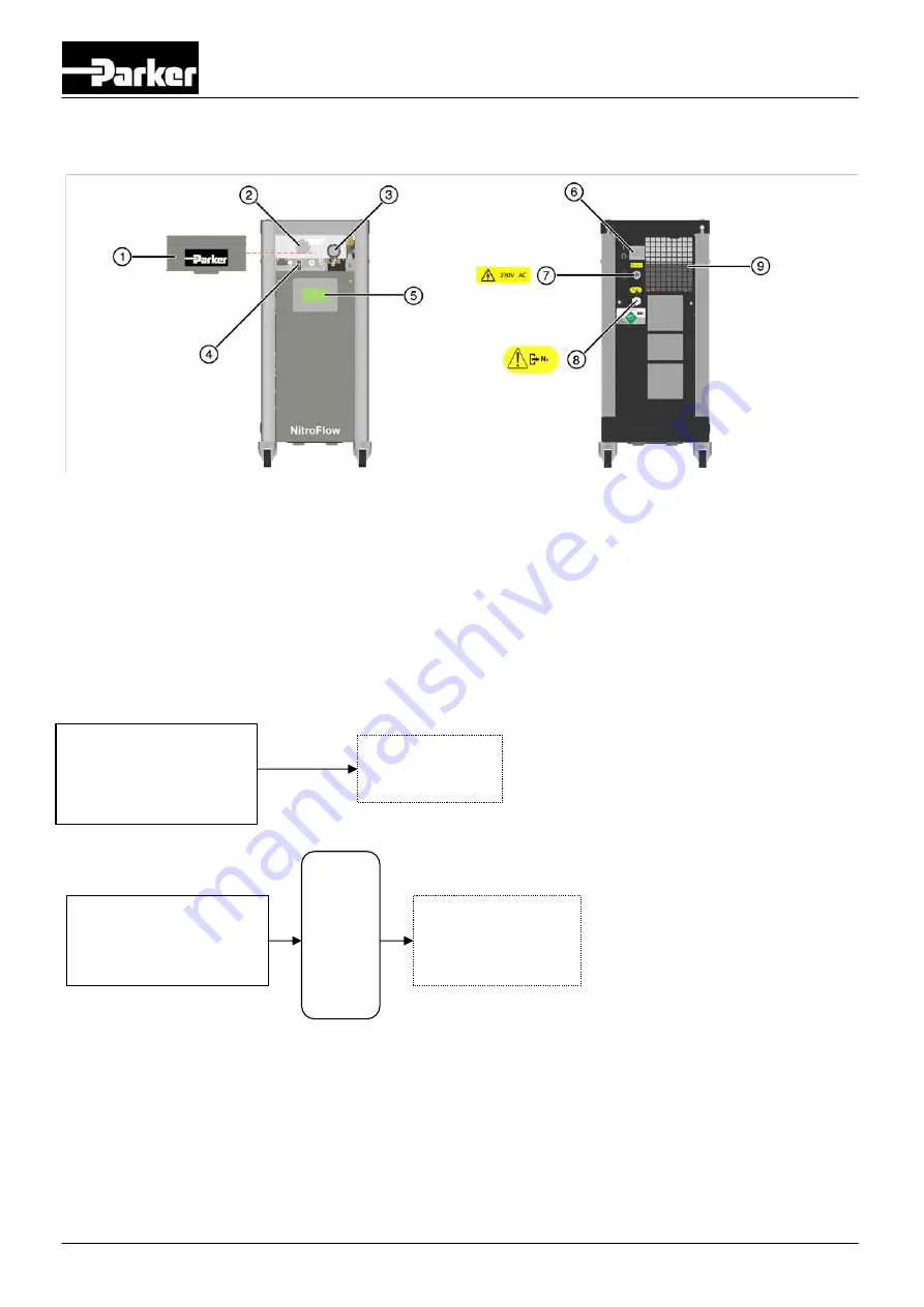
3.3 Parts 

Removable Front Cover 


Main Switch / Circuit Breaker 

Oxygen Sensor 


Electrical Supply Cable Inlet 

Pressure Control Valve (PCV) 


Nitrogen Outlet 

Purity Adjustment Valve (FCV) 


Ventilation Outlet (Keep Clear) 

Touch Screen Display 


3.4 Process 

diagram 

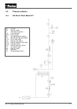
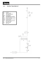
The generator can be connected directly to the nitrogen consumer (Fig. 3-3) or to a buffer vessel (Fig. 3-4). 

Fig. 3-3 

Fig: 3-4

NitroFlow

®

 Basic Mobile 

Nitrogen 
Consumer 

NitroFlow

®

 Basic Mobile

Buffer
Vessel 

Nitrogen  
Consumer

Summary of Contents for NitroFlow Basic Series

Page 1: ...Nitrogen Gas Generator NitroFlow Basic Original Language User Guide aerospace climate control electromechanical filtration fluid gas handling hydraulics pneumatics process control sealing shielding EN...

Page 2: ...otifying the customer The contents of this manual can also be changed without prior warning This manual is valid for the generator in its standard version Parker can therefore not be held liable for s...

Page 3: ...TECHNICAL SPECIFICATIONS 12 4 1 General 12 4 2 Capacity data 14 4 3 Maintenance parts 14 5 INSTALLATION 15 5 1 Transport 15 5 2 Define location 15 5 3 Unpack and check equipment 15 5 4 Connect nitroge...

Page 4: ...Flow Mobile 3 8 TROUBLESHOOTING 28 8 1 Error list 28 8 2 Alarm messages 28 9 MAINTENANCE 30 9 1 Maintenance schedule 30 9 2 Calibrate oxygen sensor 30 9 3 Cleaning 30 10 ELECTRICAL SCHEME 31 11 DECLAR...

Page 5: ...nce to this rule as well as any consequential damage loss and costs are the responsibility of the owner and the user Information All information in this manual including additional drawings and techni...

Page 6: ...or improper use The generator is in compliance with the prevailing directives and standards Only use this generator in a technically perfect condition in conformity with the purpose as described above...

Page 7: ...generator generates nitrogen as a product Oxygen enriched air is released as waste Warning x Nitrogen can cause suffocation x Oxygen enriched air leads to increased risk of fire in the event of contac...

Page 8: ...yclable Optimal sizing of buffer tanks and setting of the pressure switch will result in minimal energy consumption The lower the delivery pressure the longer the lifetime of the system According to E...

Page 9: ...0 9 argon 1 carbon dioxide water vapor and traces of other inert gasses Pressurised air A is led through hollow fibre membranes B The various air components diffuse through the porous wall of the memb...

Page 10: ...e Control Valve PCV 8 Nitrogen Outlet 4 Purity Adjustment Valve FCV 9 Ventilation Outlet Keep Clear 5 Touch Screen Display 3 4 Process diagram The generator can be connected directly to the nitrogen c...

Page 11: ...et carbon adsorber LP Air compressor RKV Start up valve M Gas separation membrane PI1 Membrane pressure indicator FCV Flow control valve HP Nitrogen compressor PCV Nitrogen pressure relief valve PSH P...

Page 12: ...en outlet C Inlet carbon adsorber LP Air compressor RKV Start up valve M Gas separation membrane PI1 Membrane pressure indicator FCV Flow control valve PCV Nitrogen pressure relief valve PSH Pressure...

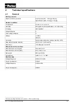
Page 13: ...ory II Altitude 2000 m 6562 ft Air quality Normal clean ambient air relative humidity 90 Max ambient relative humidity 80 to 31 C 50 at 40 C Noise level 58 dB A 1 meter 3 ft Dimensions and connections...

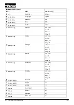
Page 14: ...Delay 30 Alarm settings O2 low Active No Stop 0 Level 0 0 Delay 30 Alarm settings Pin high Active No Stop 0 Level 13 Delay 30 Alarm settings Pin low Active No Stop 0 Level 2 Delay 30 Alarm settings P...

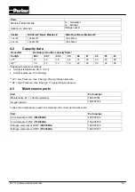
Page 15: ...30 32 38 Capacity at nominal conditions x Ambient temperature 20 C 68 F x Ambient pressure 1013 mbar a LP Low Pressure max 2 bar g 29 psig nitrogen pressure HP High Pressure max 8 bar g 116 psig nitro...

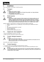
Page 16: ...nts x Minimum clearance of 50 cm on all sides back left right and top as to facilitate heat removal x Indoors x Dry x No continuous direct irradiation by sunlight x Away from heat sources x Properly v...

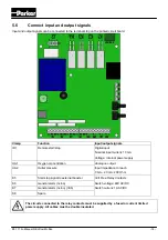
Page 17: ...nt 10 mA Voltage internal power supply UA1 Oxygen concentration Analogue output Input impedance to reach 0 mA 20 mA 200 Ohm UA2 Outlet pressure K5 Start stop signal to external booster Volt Free Relay...

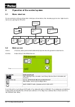
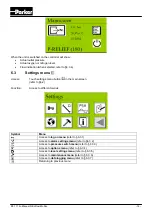
Page 18: ...ult When flashing there is an alarm touch the symbol and the current alarm will be shown Status of unit A Can be OFF RUN STAND BY ALARM P RELIEF Menu button touch to go to settings menu Switch ON OFF...

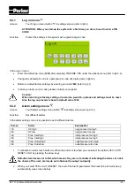
Page 19: ...ch settings menu button in the main screen refer to 6 2 Function Access to different menus Symbol Menu Access to log on menu refer to 6 3 1 Access to alarm settings menu refer to 6 3 2 Access to press...

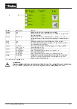
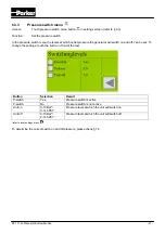
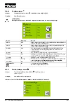
Page 20: ...de is back to default value 1234 6 3 2 Alarm settings menu Access Touch alarm settings menu button in settings screen see 6 3 2 Function Set different alarms In the alarm settings menu it is possible...

Page 21: ...s exceeded Level 0 16 O2 100 84 N2 For screen 1 6 and 2 6 this is the oxygen or nitrogen level at which the alarm is set Level 0 13 BAR 0 188 5 PSI For screen 3 6 and 4 6 This is the pressure level at...

Page 22: ...ill switch on and off can be set To change the settings touch the button in front of the text Button Selection Result P switch Yes Pressure switch is active P switch No Pressure switch is not active U...

Page 23: ...nnecting the printed circuit board to an external device Remote No Unit cannot be controlled from a remote location Pincode Yes Settings are instantly protected with a pin code Return to log on menu a...

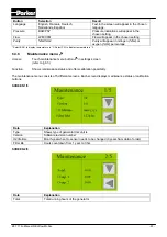
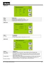
Page 24: ...to display temperature in F 6 3 6 Maintenance menu Access Touch maintenance menu button in settings screen refer to 6 3 Function Shows maintenance status and offers calibration possibility The mainten...

Page 25: ...anation O2 20 9 Calibrate O2 sensor to 20 9 Contact Parker s technical support team Flow Factor Only visible when selected Show Flow in the options menu refer to 6 3 4 and when the unit is running Cal...

Page 26: ...a Alarms as well as status of the sensors are saved on the SD card The time between the logging saving of this data to the memory card can be chosen in the data logging menu Button Selection Result In...

Page 27: ...hed off in case of no nitrogen demand 8 The purity of the generator is factory set as required To adjust the oxygen content adjust the purity control valve FCV Refer to 7 3 for instructions 9 The pres...

Page 28: ...er the pressure is set the better for energy consumption reasons and compressor life x Open the ball valve V2 at the outlet Nitrogen vessel installed Excess nitrogen will be stored generator will star...

Page 29: ...er for service Residual oxygen content too high Pressure in nitrogen storage vessel over 8 bar g because of erroneous setting of pressure switch Reset pressure switch levels Ambient temperature lower...

Page 30: ...rature sensor fails T Inlet sensor fail On Status of temperature of compressor box 1 Temp comp1 On Status of temperature of compressor box 2 Temp comp2 On Oxygen sensor needs to be calibrated Calibrat...

Page 31: ...air 2 Wait for 60 seconds 3 Then enter again the maintenance menu screen 3 5 wait until the oxygen level is stable 4 Then go to screen 5 5 and touch O2 20 9 button The system will ask for confirmatio...

Page 32: ...K3 1 114o Manual NitroFlow Mobile 31 10 Electrical scheme...

Page 33: ...K3 1 114o Manual NitroFlow Mobile 32 11 Declaration of Conformity...

Page 34: ...NOTES...

Page 35: ......

Page 36: ...arker com NL The Netherlands Oldenzaal Tel 31 0 541 585 000 parker nl parker com NO Norway Asker Tel 47 66 75 34 00 parker norway parker com PL Poland Warsaw Tel 48 0 22 573 24 00 parker poland parker...

Reviews: