background image

6

Modular Pneumatic Linear Drives OSP-L

Transport and Storage

4.1  Transport

To avoid damages during transportation and storage the linear drives have to be transported as  

described below and to be protected against dirt, humidity and violence by means of appropriate protective 

packing.


Danger caused by falling load


Incorrect transport and assembly of the OSP-L can:

•  Endanger human life.
•  Result in material damage.

Transport of OSP-L:

Avoid deflection of the OSP-L!
•  If necessary, carry long and thin cylinders with several persons.
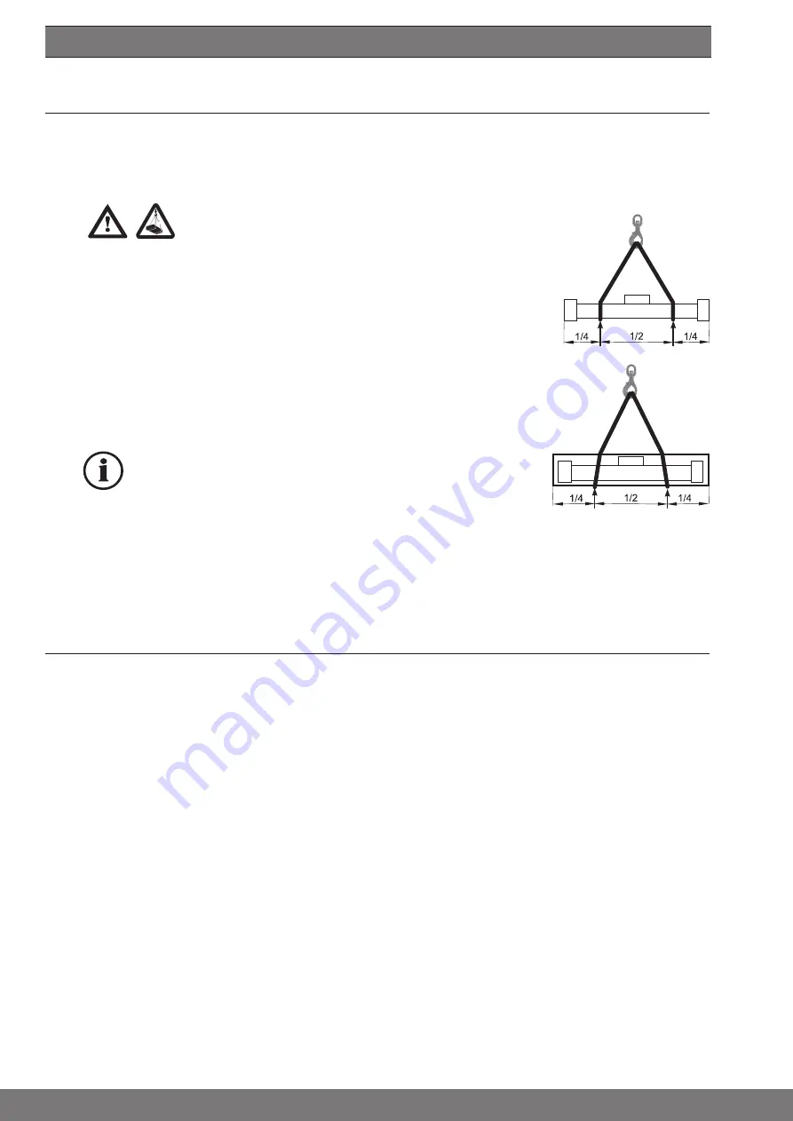
Transport of the packaged OSP-L with a crane or a forked-lift truck.  

(see illustrations on the right side)
•  Apply ropes of appropriate length with a load application ratio as shown  

or position the fork-lift truck at the appropriate points.

•  In the case of very long cylinders always use appropriate harness such  

as equalizers or fixtures in order to avoid deflection of the cylinders.


Information

Transport damage and missing parts are to be reported immediately and in  

writing to the transport company or to Parker Hannifin GmbH or to the  

delivery company.

4.2  Storage

Where storage or interim storage is involved, you must observe the following:
•  Dry, dust- and vibration-free storage.
•  On a 

flat surface.

•  Outdoors under a suitable covering.
You must avoid deflection (bending) of the OSP-L !

After sales service

 Spare parts and after sales service addresses

Refer to the last page of these Operating Instructions.

Spare parts list

For the purposes of preventive maintenance for the linear drives, we offer seal kit sets, service  

packages and spare parts (refer to Chapter 14 from page 21).
Please observe our homepage 

www.origa-service.com

unpacked

packed

Summary of Contents for OSP-L

Page 1: ...Modular Pneumatic Linear Drives OSP L Operating Instructions ORIGA SYSTEM PLUS...

Page 2: ...sioning 10 8 1 Commissioning of an OSP L cylinder 10 8 2 Commissioning of a Complete Plant 11 8 3 Re commissioning after long periods without operation 11 9 Removal from plant 11 10 Service Maintenanc...

Page 3: ...bilities The following is assumed to be the operator s organisation s responsibility compliance with EN 89 655 and the national applications compliance with the applicable national regulations for saf...

Page 4: ...ot come into contact with the com pletely vented cylinder barrel See also chapter 8 Personnel The operator of the complete plant must ensure that work on the OSP L is carried out only by authorized an...

Page 5: ...warranty he needs to notify the fault immediately and describe it precisely in his statement of complaint Under no circumstances is Parker Hannifin GmbH responsible for damage to the product itself o...

Page 6: ...ruck at the appropriate points In the case of very long cylinders always use appropriate harness such as equalizers or fixtures in order to avoid deflection of the cylinders Information Transport dama...

Page 7: ...ing pressure range pmax 8 bar Speed max 4 m s Compressed air requirements Free of water and dirt Additional lubrication with oil mist is not necessary Noise level The sound emission values sound level...

Page 8: ...in brackets refer to parts list item and exploded view drawing of the spare parts list from page 21 6 2 2 Functional Principle and Application Cylinder 25 to 63 The piston is moved by compressed air...

Page 9: ...e recommend to install the piston down installation and if necessary the use of deflectors Fasten the working load to the carrier using only the threaded holes in the carrier Position the working load...

Page 10: ...osition can be closed e g via an intake air connection or a vacuum can occur and pull the sealing band into the cylinder barrel via long supply lines This can lead to a temporary leak non permitted ac...

Page 11: ...both cushioning adjustment screws about half a turn Pressurise plant slowly in order to avoid uncontrolled dangerous movements soft start valve according in our catalogue Adjust speed with throttle n...

Page 12: ...ts in order to be able to freely move the piston If necessary completely remove the cylinder Switch off the main switch and secure it against unintentional switching on 10 1 Maintenance intervals km o...

Page 13: ...rom the inside using the piston Push piston out of cylinder bore 1 Push the sealing band to the inside for the entire length using an object that does not have sharp edges Pull inner sealing band 17 o...

Page 14: ...oth support rings together taking care to ensure that the steel bolt aluminum bolt and magnet remain in the correct position Check that piston moves smoothly as follows Insert piston into cylinder bor...

Page 15: ...of the cylinder through the bore of the sealing band Mount the second greased felt ring 24a on the support ring 25 Position the second piston seal on the support ring with the groove pointing outward...

Page 16: ...s 15 but do not tighten Grease the top ends of both cushion spigots and insert the O rings 18 19 Mount the end cap Position the end cap as needed for the air connection Tighten the opposite screws 36...

Page 17: ...the inside along the entire length using an object that does not have sharp edges With a pen simultaneously push the sealing band and piston but not the piston seal around 2 3 of the length of the pi...

Page 18: ...e clamping piece 16 on the piston side along with the sealing band as far as possible to the cap and tighten the clamping screws 15 Push the loose clamping piece 16 on the opposite side to the piston...

Page 19: ...ston seal defective 24 Replace piston seal Cylinder leaks at the end cap O ring 18 19 21 defective Replace O rings Piston moves slowly or jerking Contamination by air or abrasion Completely disassembl...

Page 20: ...rstadt Sielmingen The following related standards apply DIN EN ISO 12100 Safety of Applicanes Plant Machinery DIN EN 60204 1 Equipment for Industrial Machinery DIN EN 983 Requirements of Fluid Powers...

Page 21: ...21 EN 14 Spare Parts Lists OSP L...

Page 22: ...Spring for wiper stainless 10104 10104 10118 10104 10104 7 O Ring for scraper 10689 10689 10689 10689 10689 8 Scraper end faced 10026 10026 10026 10026 10026 9 wiper cover 10027 10085 10085 10218 103...

Page 23: ...14129 1 28 Slide shoe red 14125 2 14126 2 14127 2 14128 2 14129 2 28 Slide shoe green 14125 3 14126 3 14127 3 14128 3 14129 3 28 Slide shoe blue 14125 4 14126 4 14127 4 14128 4 14129 4 29 Keeper plat...

Page 24: ...3 Remove the guide rail 1 and clamping rail 2 from the cylinder profile Clean all the parts Centre the guide rail on the cylinder profile Fit the clamping rail 2 to the guide rail 1 and screw in the s...

Page 25: ...h no play Tighten the screws 6 in the wiper cover 7 or 17 18 with the specified torque Position the guide carriage centrally over the cylinder piston and secure the drive blocks 16 with the washers 13...

Page 26: ...Remove guide rail 5 from the cylinder barrel Dismantling the Clamping Profile 4 To dismantle the clamping profile 4 remove one of the endcaps of the OSP L cylinder Refer to the operating instructions...

Page 27: ...e Carriage 9 Position guide carriage 9 onto the carriers 8 mind alignment towards the piston Loosely fix with the screws 10 and the washers 11 and then Note Press guide carriage 9 against the sanded s...

Page 28: ...e in accordance with the below table using three times the subset 1 grease carrier with the first subset in accordance with the table 2 slide the carrier with 3 up and down strokes by at least three t...

Page 29: ...83 10683 5 Support strip 10571 10590 10570 10798 11547 6 screw 2742 2742 1062 2742 2742 6 screw stainless 3716 3716 1063 3716 3716 7 Wiper cover 1661 1681 10487 10504 8 Felt 1619 1665 10665 10665 1154...

Page 30: ...71 23 carrier 11542 16 1 3 Replacement Assemblies Ident No Item Description SL 25 SL 32 SL 40 SL 50 SL 63 5 6 7 8 Guide carriage complete 11401 11404 11407 11410 9 10 11 12 14 Guide carriage complete...

Page 31: ...e 13517 13518 13519 13520 5 Guide rail 6 Screw for Guide rail 7 Washer for Guide rail 8 Carrier 9 Guide carriage 10 Screw for carriage 11 Washer for carriage 3954 3954 4373 3789 12 Grease nipple 13 Sc...

Page 32: ...x 90 to position connector 6 as required to do this remove knurled nut 7 turn solenoid 8 to desired position and retighten knurled nut Speed Regulation The throttle silencer 12 can be exchanged with e...

Page 33: ...alve 11890 11890 11890 11890 6 Plug 10 50 V 11894 11894 11894 11894 6 Plug 70 250 V 11895 11895 11895 11895 7 Knurled nut 651 651 651 651 Spring washer 652 652 652 652 8 Solenoid coil for 24 V and 60...

Page 34: ...0 6 7 8 Complete Integrated 3 2 way valve VOE 11840 11866 11855 11857 14 15 but without Plug knurled nut solenoid and end cap screws 17 2 4 Lubrication Ident No Item Description OSP L25 OSP L32 OSP L4...

Page 35: ...35 EN Notes...

Page 36: ...l 39 02 45 19 21 parker italy parker com KZ Kazakhstan Almaty Tel 7 7272 505 800 parker easteurope parker com NL The Netherlands Oldenzaal Tel 31 0 541 585 000 parker nl parker com NO Norway Asker Tel...

Reviews: