Parker Hannifin Corporation
Hydraulic Pump and Power Systems Division
Marysville, Ohio USA
Bulletin HY28-2708-02/SVC/EN | July 2019
Medium Pressure Axial Piston Pumps
P1/PD B-mod Service Information
34
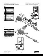
1. Remove and discard all O-rings. Install new O-rings on SAE boss plugs (#13),
and install SAE boss plugs (#13) into their respective cavities.
2. Apply a light film of oil to the main compensator (Pmax) spool outer spring guide
O-ring (#7), and install it on the Pmax spool outer spring guide (#6).
3. Apply a light oil film to the Pmax outer cap O-ring (#8), and install it on the
Pmax outer cap (#9).
4. Apply petroleum jelly to the Pmax outer spring guide (#6) and push it into Pmax
outer cap (#9).
NOTE:
Make sure the orientation of the guide matches the orientation in the control
assembly exploded view section.
5. If possible, turn the compensator housing so that the spool bores face upward.
Install set screw (#2) and Pmax spool (#1). Next, place Pmax inner spring guide
(#3) inside the Pmax spool bore on top of the Pmax spool (#1). Make sure
the orientation of the guide matches the orientation in the control assembly
exploded view section. Place the Pmax outer spring (#5) on top of the inner
spring guide (#3) in the spool bore. Place the Pmax inner spring (#4) inside the
outer spring (#5) so that it sits on top of the inner spring guide (#3).
6. Thread the Pmax outer cap assembly from steps 2-4 into the Pmax spool bore.
As the assembly is threaded in the bore, the outer spring (#5) should seat itself
on the outer spring guide (#6).
7. Install the Pmax adjustment screw (#11) and lock nut (#10) into the Pmax outer
cap (#9).
8. Install the “X” port set screw/orifice (#16) into the “X” port located on top of the
compensator.
9. For “C” compensators install the SAE boss plug (#18) in the “X” port on top of
the compensator, and set screw plug (#17) into the control port on the bottom of
the compensator. Install boss plug (#19) in the differential spool bore.
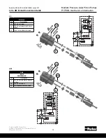
Steps 10-15 apply to the “L” or “AM” compensators.
10. Apply a light film of oil to the differential outer spring guide O-rings (#25 &
26) and install them on the differential outer spring guide (#24).
11. Apply a light film of oil to the differential cap O-ring (#27) and install it on
the differential cap (#28).
12. Apply petroleum jelly to the differential outer spring guide (#24) and push it
into the differential cap (#27).
NOTE:
Make sure the orientation of the guide matches the orientation in the
control assembly exploded view section.
13. With compensator housing upright, if possible, so that the bore faces
upward, insert the differential spool (#20) into the spool bore. Next, place
the differential inner spring guide (#21) on top of the differential spool (#20)
inside the spool bore. Make sure the orientation of the guide matches the
orientation in the control assembly exploded view section. Then place the
differential outer spring (#23) on top of the differential inner spring guide
(#21). Then place the differential inner spring (#22) inside the differential
outer spring (#22) so that it sits on the differential inner spring guide (#21).
14. Thread the differential cap assembly from step 12 into the differential spool
bore. As the assembly is threaded in the bore, the outer spring (#23) should
seat itself on the outer spring guide (#24).
15. Install the differential adjustment screw (#30) and lock nut (#29) into the
differential outer cap (#28).
16. Install the five O-rings (#14) on compensator ports on the compensator.
17. Using bolts (#12), bolt down compensator assembly onto pump housing.
Make sure locating pin (#15) is properly aligned to locating pin hole on the
compensator mounting pad on the pump housing.
Compensator Assembly
Carefully clean and dry all parts prior
to assembly. Use caution to ensure
that spools and other parts are not
damaged during the cleaning process.
Use clean oil to lubricate seals and
spools for easier assembly.
Compensator Procedures


