background image

Parker Hannifin Corporation

Hydraulic Pump and Power Systems Division

Marysville, Ohio USA

Bulletin HY28-2708-02/SVC/EN | July 2019

Medium Pressure Axial Piston Pumps

P1/PD B-mod Service Information

30

7

9

27

22

29

1

5

3

20

19

18

17

16

21

30

10

24

28

26

19

20

25

2

4

2

6

11

12

23

13

14

15

8

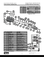
C0* Pressure Compensator Control  
with Unloading Valve

L0* Load Sense Control  
with Unloading Valve

6

Electronic Unload Control B-mod Exploded View

Item

Torque

5

11 ft lbs

6

40 in lbs

8

6 ft lbs

9

22 ft lbs

10

5 ft lbs

18

85 ft lbs

20

70 in lbs

28

50 ft lbs

29

50 ft lbs

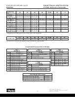
Control Assembly  

Part Numbers

C03 

S2E-20764-5T

C06

S2E-20765-5T

L03 SAE

S2E-20756-5T 

L03 BSPP

S2E-20757-5T

L03 Metric

S2E-20758-5T

L06 SAE

S2E-20759-5T

L06 BSPP

S2E-20760-5T

L06 Metric

S2E-20761-5T

Summary of Contents for P1/PD Series

Page 1: ...P1 PD Series B Mod Service Information Medium Pressure Axial Piston Pumps Bulletin HY28 2708 02 SVC EN Effective July 2019 Replaces March 29 2019...

Page 2: ...oded View 17 C0 to L0 B mod Conversion Guide 18 C0 to L2 B mod Conversion Guide 19 C0 to AM B mod Conversion Guide 20 L0 L2 to C0 B mod Conversion Guide 21 L0 to L2 B mod Conversion Guide 22 L2 to L0...

Page 3: ...two exceptions Both exceptions are on the 45 60cc pumps One exception is when the load sense L or remote compensator AM is used in combination with the torque limiting control ALT or AMT The ALT or A...

Page 4: ...pattern size remains the same No change to housing casting required Standard NG6 D03 Pattern Custom Control Pad Pattern Pressure Limiter C00 C10 Left Pressure sense L00 L20 Left Pilot operated pressur...

Page 5: ...ee flow through the pump An undersize inlet line will prevent the pump from operating properly at full rated speed An undersize outlet line will cause back pressure and cause heat generation and incre...

Page 6: ...8 1 71 45 2 75 60 3 66 75 4 58 85 5 19 100 6 01 140 8 54 Outlet Pressure Continuous 280 bar 4060 psi 250 bar 3600 psi 280 bar 4060 psi Intermittent 320 bar 4640 psi 300 bar 4350 psi 320 bar 4640 psi P...

Page 7: ...View Item 18 28 Torque Torque 2 52 ft lbs 52 ft lbs 3 45 ft lbs 45 ft lbs 5 6 ft lbs 6 ft lbs 6 25 in lbs 25 in lbs 16 12 in lbs 70 in lbs 19 45 ft lbs 45 ft lbs 30 30 in lbs 30 in lbs 34 70 in lbs 7...

Page 8: ...mod Service Information 8 045 B mod Pump Exploded View Item 45 Torque 1 63 ft lbs 2 45 ft lbs 5 6 ft lbs 6 25 in lbs 11 105 ft lbs 14 105 ft lbs 16 10 ft lbs 19 46 ft lbs 30 30 in lbs 34 70 in lbs 36...

Page 9: ...etaining ring internal 21 1 787635 03E 94387 0 03E 94350 0 Barrel hold down spring 22 2 1 045 786996 03E 94388 0 03E 94351 0 Barrel hold down washer 23 1 03E 94717 0 03E 94375 0 03E 94338 0 Barrel 24...

Page 10: ...75 85 100 140 Torque Measured in ft lbs 1 100 100 170 205 2 45 45 45 45 5 6 6 6 6 6 2 1 2 1 2 1 2 1 11 105 105 136 170 14 105 105 136 170 30 2 8 2 8 2 8 2 8 34 5 8 5 8 5 8 5 8 36 75 85 85 135 37 14 1...

Page 11: ...LUDED IN ITEM 18 Tapered roller bearing cone 20 1 356 65152 0 356 65144 0 356 65144 0 356 65146 0 356 65147 0 Retaining ring internal 21 1 03E 94049 0 03E 93145 0 03E 93145 0 03E 93795 0 03E 93959 0 B...

Page 12: ...Description 2 1 Plug with O ring no volume stop 54 1 Adjusting screw 55 1 Adjusting screw lock nut 56 1 Volume stop plug 57 1 Volume stop plug O ring 58 1 Backup ring 59 1 Volume stop rod O ring 60 1...

Page 13: ...74 0 03E 93947 0 695 00237 0 SAE A 11 Tooth S2E 19726 0 S2E 19391 0 03E 94943 0 03E 94724 0 03E 94724 0 03E 94657 0 03E 95706 0 695 00237 0 SAE B 13 Tooth S2E 19365 0 03E 94945 0 03E 93277 0 03E 93277...

Page 14: ...ter cap 10 1 340 00063 0 Pmax adjustment lock nut 11 1 361 08275 0 Pmax M6x22 adjustment screw 12 4 361 07253 8 M5 x 45 SHCS 13 3 108X2V SAE Boss Plug O ring 14 5 Available in kit only Compensator tef...

Page 15: ...3 0 Pmax adjustment lock nut 11 1 361 08275 0 Pmax M6x22 adjustment screw 12 4 361 07253 8 M5 x 45 SHCS 13 3 108X2V SAE Boss Plug O ring 14 5 Available in kit only Compensator teflon O ring 15 1 325 3...

Page 16: ...orifice 20 1 03E 95926 0 Differential spool 21 1 Available in kit only Differential inner spring guide 22 1 Available in kit only Differential inner spring 23 1 Available in kit only Differential oute...

Page 17: ...set screw 20 1 03E 95860 0 Differential spool 21 1 Available in kit only Differential inner spring guide 22 1 Available in kit only Differential inner spring 23 1 Available in kit only Differential o...

Page 18: ...plug O ring SAE 19 Boss plug O ring Add Kit 1 S2E 20463 5K Item Description 21 Differential inner spring guide 22 Differential inner spring 23 Differential outer spring 24 Differential outer spring g...

Page 19: ...SAE 19 Boss plug O ring Add Kit 1 S2E 20463 5K Item Description 21 Differential inner spring guide 22 Differential inner spring 23 Differential outer spring 24 Differential outer spring guide 25 Diff...

Page 20: ...8 Boss plug O ring SAE 19 Boss plug O ring Add Kit 1 S2E 20463 5K Item Description 21 Differential inner spring guide 22 Differential inner spring 23 Differential outer spring 24 Differential outer sp...

Page 21: ...se differential spool 21 Differential inner spring guide 22 Differential inner spring 23 Differential outer spring 24 Differential outer spring guide 25 Differential inner spring guide O ring 26 Diffe...

Page 22: ...28 2708 02 SVC EN July 2019 Medium Pressure Axial Piston Pumps P1 PD B mod Service Information 22 L0 to L2 B mod Conversion Guide X B BG D3 D2 D1 A X B BG D3 D2 D1 A L0 L2 16 16 Remove Item Descriptio...

Page 23: ...28 2708 02 SVC EN July 2019 Medium Pressure Axial Piston Pumps P1 PD B mod Service Information 23 L2 to L0 B mod Conversion Guide X B BG D3 D2 D1 A X B BG D3 D2 D1 A L2 L0 16 16 Remove Item Descriptio...

Page 24: ...m Pressure Axial Piston Pumps P1 PD B mod Service Information 24 L0 to AM B mod Conversion Guide X B BG D3 D2 D1 A X B BG D3 D2 D1 A L0 AM 2 20 20 Remove Item Description 2 M5 x 6 set screw 20 Load se...

Page 25: ...PD B mod Service Information 25 L2 to AM B mod Conversion Guide 16 16 X B BG D3 D2 D1 A X B BG D3 D2 D1 A L2 Remove Item Description 2 M5 x 6 set screw 16 M6 x 6 set screw with 0 4mm orifice 20 Load s...

Page 26: ...al inner spring guide 22 Differential inner spring 23 Differential outer spring 24 Differential outer spring guide 25 Differential inner spring guide O ring 26 Differential inner spring guide O ring 2...

Page 27: ...m Pressure Axial Piston Pumps P1 PD B mod Service Information 27 AM to L0 B mod Conversion Guide X B BG D3 D2 D1 A X B BG D3 D2 D1 A AM 2 20 20 Remove Item Description 2 M5 x 6 set screw with 0 8mm or...

Page 28: ...PD B mod Service Information 28 X B BG D3 D2 D1 A AM L2 2 16 16 20 20 X B BG D3 D2 D1 A Remove Item Description 2 M5 x 6 set screw with 0 8mm orifice 16 M6 x 6 set screw 20 AM remote differential spoo...

Page 29: ...ter sleeve 67 1 Compression spring 68 1 Adjustment screw O ring ARP 111 69 1 Torque limiter screw 70 1 Torque limiter spring 71 1 Torque limiter guide 72 1 Torque limiter spool 73 1 Torque limiter spo...

Page 30: ...13 14 15 8 C0 Pressure Compensator Control with Unloading Valve L0 Load Sense Control with Unloading Valve 6 Electronic Unload Control B mod Exploded View Item Torque 5 11 ft lbs 6 40 in lbs 8 6 ft l...

Page 31: ...14 1 Available in kit only Available in kit only Pmax inner spring 15 1 Available in kit only Available in kit only Pmax outer spring guide 16 1 675 00009 0 675 00009 0 Pmax outer spring guide O ring...

Page 32: ...070 0K S2E 18701 0K S2E 18484 0K S2E 18488 0k S2E 18492 0K CCW Industrial PD w Ripple Chamber S2E 19208 0K S2E 19212 0K S2E 19127 0K Rotating Group Kit includes barrel s a pistons retainer washer pins...

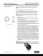
Page 33: ...ne closer to the top of the controller body Remove the inner spring guide 21 and differential compensator spool 20 from the housing 4 To disassemble the Pmax cap 9 and outer spring guide 6 assembly th...

Page 34: ...e bottom of the compensator Install boss plug 19 in the differential spool bore Steps 10 15 apply to the L or AM compensators 10 Apply a light film of oil to the differential outer spring guide O ring...

Page 35: ...move these items from inside the pump if they remained in the pump when the port block was removed Remove and discard the white Teflon O rings 8 on the port block These seals should be replaced every...

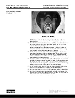
Page 36: ...to Step 7 of the assembly procedure 9 Remove the cam 29 from the housing by tilting it and carefully extracting it from the pump housing See Figure 2 Pump Disassembly Procedure Continued Figure 2 Lar...

Page 37: ...on shoes Any marks beyond light polishing indicate that replacement is necessary Check the surface of the spherical area of the retainer plate and the spherical guide washer 25 Inspect the back surfac...

Page 38: ...end play 0 004 in 0 10 mm Min Shoe Flange Thickness 0 233 in 5 91 mm 075 085 5 98mm 03E 93151 0 5 57 in 141 5 mm 03E 93145 0 2 50 in 63 7 mm 03E 93129 0 S2E 17003 0 Max End Play 0 004 in 0 10 mm Min S...

Page 39: ...p skip step 3 For the 18 and 28cc pumps turn the housing over Use installation tool T1 and press the shaft seal 39 in the seal bore Install the snap ring 40 into the groove in the housing seal bore 4...

Page 40: ...oo soon and the guides will not be able to be fully torqued 13 Apply a light film of oil into the piston bores Lightly lubricate the spherical surface of the guide ball Install the nine pistons into t...

Page 41: ...ning up the slot on the port plate with the port plate locating pin 7 See Figure 7 15 Install the large O ring 4 into the groove on the port block 3 Install the three Teflon O rings 8 on the pressure...

Page 42: ...e barrel 23 Remove tool T6 as the barrel is slid onto the shaft This ensures all three barrel pins 24 are held in place as the rotating group is installed on the shaft 20 Carefully install the assembl...

Page 43: ...ing cone 32 and shaft 28 into the housing Tool T3 can be used to help protect the shaft seal from damage from the splines when installing the shaft Install the rear shaft bearing cone 19 on the shaft...

Page 44: ...1354in 03E 93567 0 03E 94150 0 03E 93971 0 3 52 mm 139in 3 62 mm 142 in 3 52 mm 1386 in 03E 93568 0 03E 94151 0 03E 93972 0 3 63 mm 143 in 3 70 mm 145 in 3 60 mm 1417 in 03E 93569 0 03E 94152 0 03E 93...

Page 45: ...uide bore 17 Install the control flow housing set screw 34 into the proper passage For proper location see Figure 12 in the rotation change section 18 Apply a light layer of petroleum jelly to the bac...

Page 46: ...m surface of the cam must be on the same side as the three pressure communication holes on the main housing Cam assembly is not affected by pump rotation direction 22 Position the pump horizontally an...

Page 47: ...0 in 63 5 mm 2 230 in 56 6 mm 1 703 in 43 3 mm 0 550 in 14 0 mm 140 213 0 004199 3 375 in 85 7 mm 2 780 in 70 6 mm 2 10 in 53 4 mm 0 750 in 19 1 mm T1 Seal Installation Tool T2 Front Bearing Installat...

Page 48: ...195 4 25 in 108 mm 2 25 in 57 1 mm 1 00 in 25 4 mm 10 1 373 in 34 90 mm 0 885 in 31 75 mm 100 SAE 213 0 004206 4 25 in 108 mm 2 78 in 70 6 mm 1 00 in 25 4 mm 10 1 703 in 43 26 mm 1 5 in 38 1 mm 100 IS...

Page 49: ...140 213 0 004197 3 687 in 93 7 mm 3 515 in 89 3 mm 15 Pump Size A B C D E 018 0 795 in 20 2 mm 2 84 in 72 0 mm 0 756 in 19 2 mm 2 32 in 59 0 mm 1 18 in 30 0 mm 028 0 902 in 22 9 mm 2 95 in 75 0 mm 0...

Page 50: ...ormation 50 Pump Model Part No A B C 060 075 085 213 0 004193 2 120 in 53 8 mm 1 918 in 48 7 mm 12 100 213 0 004205 2 562 in 65 1 mm 2 335 in 59 3 mm 15 140 213 0 004198 2 80 in 71 1 mm 2 562 in 65 1...

Page 51: ...t the correct port plate Use Figure 7 to verify that you have the correct rotation port plate For the 18 28 45cc units that are side ported with no thru drive make sure you select the appro priate rip...

Page 52: ...the control piston 15 and bias piston 12 and spring 13 need to be swapped 6 For the 45cc units and larger the bias guide 11 and control guide 14 are different so remove the guides control and bias pi...

Page 53: ...to minimum by turning the Pmax adjustment screw counter clockwise until the spring force is not felt For pumps with the L or AM controls turn the differential adjustment clockwise until it bottoms out...

Page 54: ...let pressure will be the stand by pressure 13 Use steps 13 15 for remote compensator pumps AM control option Close the load relief valve to deadhead the pump and adjust the remote relief valve so that...

Page 55: ...Check reservoir for cleanliness Drain and clean as required Check fluid level and fill as required with filtered fluid to a minimum ISO cleanliness level of 20 18 14 Fill pump case with clean oil prio...

Page 56: ...uid too heavy Shaft speed too high Inlet line too small Inlet strainer too small Inlet strainer too dirty Operating altitude too high Inlet pressure too low Misaligned shaft Faulty installation Distor...

Page 57: ...tiveness with chemical aging Improper repair Incorrect parts Incorrect procedures dimensions finishes Unwanted water in fluid Condensation Faulty breather strainer Heat exchanger leakage Faulty clean...

Page 58: ...osity cSt x 1 0 mm2 sec mm2 sec x 1 0 cSt SSU cSt x 4 25 14 20 cSt 99 SSU FLUID POWER FORMULAS Pump input torque lbs in pressure psi x displacement in3 rev 2 x mech eff Pump input power hp rpm x in3 r...

Page 59: ...reby offered for sale by Parker Hannifin Corporation its subsidiaries or its authorized distributor This offer and its accepteance are governed by the provisions stated in the detailed Offer of Sale e...

Page 60: ...lic Pump and Power Systems Division 14249 Industrial Pkwy Marysville OH 43040 USA phone 937 644 4435 fax 937 642 3639 www parker com hps Bulletin HY28 2708 02 SVC EN Effective 07 19 2019 Parker Hannif...

Reviews: