7
!
CAUTION:
Failure to keep a Converter and Flow Detector combination paired
properly will cause a loss of system accuracy and performance.
Installation
Requirements for Installation Site of the Signal Converter:
• Temperature range 0 - 50°C (32 - 122°F)
• Do not use in direct sunlight
• Humidity: 95% R.H. or less non-condensing
• Install unit in an area free of electromagnetic interference. Isolate power to unit from circuits containing
devices that draw large current or create line noise.
• Converter should not come in contact with fluids
Mounting and Removal:
Step 1
Connect flow detector coaxial cables with BNC connectors to converter.
Step 2
Confirm that the converter body and the terminal-block plug socket are firmly fixed with the
lock arm of the main body.
Step 3
When separating, push the lock arm and pull to the front.
Wiring of Flow Detector:
Step 1
Converter plugs into terminal plug socket.
Step 2
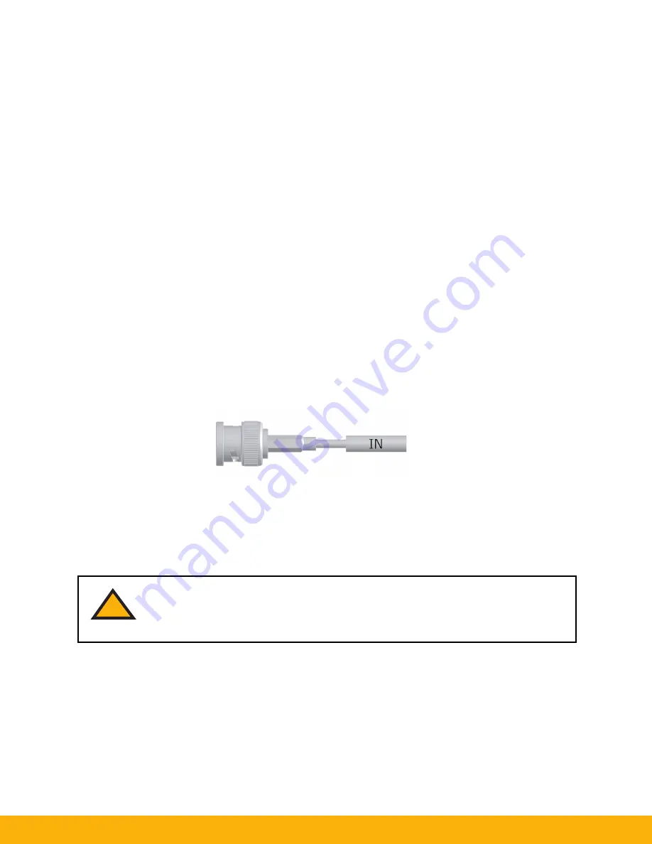
The polarity of the BNC connector is shown in the figure below. Connect Red to IN (upstream
side) of the converter, and Black to OUT (downstream side). If strain relief is not color
coded refer to cable identifiers. Lock the BNC connectors securely.
Step 3
When installing multiple PFM1 systems, pay attention to ensure that the detector and converter
combination remain properly paired together.
Summary of Contents for PAFC-100
Page 23: ...Notes 23 ...


