background image

www.parflexsystem.com

S

IMPLE

, R

ELIABLE

 & F

AST

Design and Installation Guide

Bulletin No. 4660-PGP2T
Effective Date September 2007

Summary of Contents for Parflex

Page 1: ...www parflexsystem com SIMPLE RELIABLE FAST Design and Installation Guide Bulletin No 4660 PGP2T Effective Date September 2007 ...

Page 2: ... or improper Application of CSST used to convey fuel gas such as natural gas or propane in building structures can cause death personal injury and property damage Possible consequences of failure or improper Application of these Products include but are not limited to Holes and leaks in the CSST caused by electrical arcing between the tubing and an adjacent metal object such as a furnace duct caus...

Page 3: ...guration and Sizing 3 1 System Configuration 3 1 1 System Planning 16 Sizing and Pressure Loss 16 Series System 16 Parallel System 17 3 1 2 Pressure System 17 Low Pressure System 17 Medium Pressure System 18 Dual Pressure System 18 Elevated Pressure System 18 3 2 System Sizing Methods and Examples 3 2 1 Sizing Methods 19 3 2 2 Longest Length Series System Example Low Pressure 19 3 2 3 Longest Leng...

Page 4: ...eplace 41 4 7 Manifold Stations 45 4 7 1 Configurations 45 4 7 2 Allowable Locations 45 4 8 Line pressure Regulators 46 4 8 1 Installation requirements 46 4 8 2 Venting 46 Vent Limiter 46 Vent Line Sizing Requirements 46 4 8 3 Adjustments 46 4 8 4 Over Pressurization Protection 47 4 9 Underground Installations 47 4 10 Electrical Bonding and Grounding 48 4 11 Additional Recommended Equipotential Bo...

Page 5: ...ller to seek technical assistance from other sources The techniques included in this document are recommended practice for general applications System design and installation practices must comply with all applicable local fuel gas codes and building codes Where conflict exists between the recommended practice and local codes the local code must take precedence unless a variance is obtained from t...

Page 6: ...ms d The small diameter CSST is suitable for use with elevated pressure systems above 1 2 psi up to 5 psi e Different practices are required in the handling and installation of semi rigid tubing compared to steel pipe The Parflex System may be Applied in combination with schedule 40 steel pipe using approved threaded couplings at the interface CSST can be used for both the low pressure system belo...

Page 7: ...56 0 75 0 98 1 4 1 63 2 35 Pitch Corrugations per Foot 76 67 51 49 45 40 Recommended Min Bend Radius 3 3 3 5 5 6 Length of Reels Ft 50 1000 50 1000 50 1000 50 500 50 300 75 150 Weight of Reels Lbs 27 109 36 145 43 165 38 295 37 119 76 128 Mechanical Fittings Straight Fitting Tube to Male Pipe Connector FastMate U S Patent No 6 908 114 Flareless Quick Connect Fittings for Parflex Tubing Part No Tub...

Page 8: ... lbs 2UFM 6B 3 8 7 8 7 8 2 61 27 2UFM 8B 1 2 1 1 8 1 1 8 2 83 55 2UFM 12B 3 4 1 7 16 1 3 8 3 19 68 2UFM 16B 1 1 3 4 1 5 8 3 23 88 2UFM 20B 1 1 4 2 1 4 2 1 8 3 86 2 80 2UFM 32B 2 3 1 4 3 5 00 5 50 Part No Tube Size Tube Size Tube Size Nut Hex Nut Hex Nut Hex Assembled Length Tee Drop Length Weight A B C A B C D E lbs 2TFM 12 8 8B 1 2 1 2 3 4 1 1 8 1 1 8 1 7 16 4 21 2 44 1 47 2TFM 16 8 8B 1 2 1 2 1 ...

Page 9: ...lange Fitting Shown with optional flange mounting bracket FMB 1 and Section 2 0 System Components Elbow Flange Fitting Tube to Flange Mount 90 Elbow Male Pipe Connector Fitting Part No Malleable Part No Galvanized Flange Part No Tube Size Flange Dia Nut Hex Assembled Length NPTF Thread Size Elbow Drop Length Weight lbs A B C D E 2NFEFM 8B 8 CFL 8 CFLG 1 2 4 1 3 8 2 07 1 2 14 1 48 96 2NFEFM 12B 12 ...

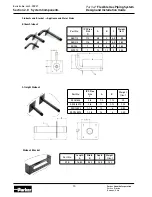
Page 10: ... System Components Elbow Stubout Straight Stubout Part No IPS Pipe Size C A B Weight lbs SSO3 4X6 3 4 7 0 1 13 90 SSO3 4X10 3 4 11 1 13 1 30 SSO125X6 1 1 4 10 4 2 50 SSO125X12 1 1 4 16 4 3 60 Part No IPS Pipe Size D A B C Weight lbs ASO1 2 1 2 4 5 2 4 5 85 ASO3 4 3 4 4 5 2 4 5 1 80 SO1X6 1 8 6 5 1 50 SO1X10 1 12 10 5 2 00 Part No Length A Width B Depth C Weight lbs STB 14 50 5 20 3 25 1 90 Stubout...

Page 11: ...t PGPSC 6 50FT 0 63 0 77 2 3 4 17 5 50 PGPSC 8 50FT 089 1 08 3 1 4 26 50 PGPSC12 25FT 1 19 1 39 3 3 4 41 60 25 PGPSC 16 25FT 1 51 1 77 4 1 2 60 25 PGPSC 20 25FT 2 25 2 45 6 1 2 92 25 Part No Nom ID Nom OD Min Bend Radius in Weight 100 ft lbs Pack age Qty pcs PGPSC 6 12IN 0 63 0 77 2 3 4 15 50 PGPSC 8 12IN 089 1 08 3 1 4 26 50 PGPSC 12 12IN 1 19 1 39 3 3 4 45 25 PGPSC 16 12IN 1 51 1 77 4 1 2 62 25 ...

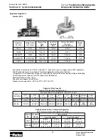
Page 12: ...ht lbs 325 3L 3 76 1 2 x 1 2 1 8 27 8 19 0 80 325 5A 4 7 8 124 3 4 x 3 4 3 8 18 8 19 2 02 325LP 3 3 76 1 2 x 1 2 1 8 27 11 26 6 0 80 325LP 5A 4 7 8 124 3 4 x 3 4 3 8 18 11 26 6 2 02 325 7 6 1 8 156 1 1 4 x 1 1 4 1 2 14 11 26 6 3 65 Regulator Flow Capacity Flow in ft3 hr m3 hr 0 64 Sp gr gas Regulator Part No Pressure Drop Across Regulator Inch W C or psi 0 3 0 7mbar 0 5 1 2mbar 1 0 2 5mbar 3 0 7mb...

Page 13: ... code accepted materials Manifold Mounting Bracket Part No WMB 1 Part No A B C D E F NPT Thread NPT Weight lbs BM4P 8 9 56 1 31 1 31 2 31 1 31 3 4 14 Female 1 2 14 4 ports 2 10 4PM 8 11 19 1 31 2 13 2 31 2 13 3 4 14 Male 1 2 14 4 ports 2 05 Malleable Iron Manifold Coated to Prevent Rust Part No 4PM 8 Gas Load Center 1 Metal enclosure with pre installed mounting bracket 2 Metallic face plate All pi...

Page 14: ...ves Appliance Connectors Part No 103029 Quick disconnect 3 375 valve for interior appli ance installations Gas connection with 1 2 inch FPT 90 inlet and plug with 3 8 inch FPT outlet Part No GASOUTLET Complete kit includes valve with mount ing plate enclosure and cover housing For outdoor appli ance installations Part No Tube Size Wt lbs Replacement Kit PGPCT SM 3 8 1 2 1 05 PGP SCR PGPCT LG 3 4 1...

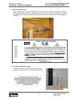
Page 15: ...ystem must be made only by a trained and qualified installer using special installation procedures and using only the same brand and type of components Improper modification or repair of this pipe system can cause a release of gas resulting in asphyxiation explosion and fire SHUT OFF GAS AT SERVICE PANEL OR METER IF PIPING OR CONNECTORS ARE DAMAGED OR LEAKING This piping system must be properly el...

Page 16: ...es water column set at the second stage regulator outside the building Higher supply pressures will allow reduced tubing size Check with your propane supplier and local building code authority 3 Prepare a dimensioned sketch of the installation showing the location of each appliance and possible piping routes 4 Determine the load BTU hr or CFH demand and the minimum required inlet pressure for each...

Page 17: ...y pressure measured at the appliance The second stage regulator for propane systems is often set at 11 inches WC and a 1 2 inch WC maximum pressure drop is allowed through each line A low pressure series arrangement typically requires larger diameter tubing to meet appliance demands Section 3 0 System Configuration Sizing Parallel System Parallel system layouts utilize a central distribution manif...

Page 18: ...iance inlet pressure requirement Dual Pressure System The dual pressure system incorporates two pressure regulators down stream of the meter The primary pressure set by the service regulator at the meter is normally 2 psi but can be higher or lower based on local code and gas company policy The secondary pressure set by the pounds to inches regula tor is less than 1 2 psi normally 8 inches WC whic...

Page 19: ...est length from the meter to the farthest appliance is 1 2 inch water column The gas supplied has a specific gravity of 60 and an energy content of 1 cubic foot per hour equals 1 000 BTU per hour Reference Sizing Table 1 Section 7 1 for sizing charts 1 Determine the total gas load for each appliance in cubic feet per hour Furnace 75 CFH 75 000 BTUH 1000 BTUH per CFH Oven range 50 CFH 50 000 BTUH 1...

Page 20: ...ch PGP 8 to run Section D 7 Sizing Section E The total appliance load is 50 CFH Using the longest length method the length from the range oven is 20 ft A 8 ft B 10 ft E 2 ft From Table 1 under the 20 ft length column we find that 1 2 inch PGP 8 has flow capacity above 50 CFH 64 Use 1 2 inch PGP 8 to run Section E 8 Sizing Section F The total appliance load is 75 CFH The length is 14 ft A 8 ft F 6 ...

Page 21: ... is 50 CFH and the length is 80 ft 20 ft 100 ft Referring to Table 8 under the 100 ft length column we find that 1 2 inch PGP 8 has capacity above 50 CFH 98 Use 1 2 inch PGP 16 to run Section B 3 Sizing Section C Section C supplies the furnace The total load is 75 CFH and the total length is 80 ft 5 ft 85 ft Refer to Table 8 under the 85 ft column Since 85 ft does not appear in the length column u...

Page 22: ... a single 325 3L regulator has an insufficient flow rate capacity A larger 325 5A regulator should be used 2 Sizing Section A Meter to Regulator Section A must be sized to handle all appliance loads and sup ply the pressure reducing pounds to inches regulator The total load is 184 CFH and the length is 80 ft The supply pressure is 2 psig and the pressure drop is 1 psig Referring to Table 9 meter t...

Page 23: ... last HVAC Unit The total appliance load is 225 225 225 225 900 CFH Using the longest length sizing method the length is 150 ft Referring to Table 11 under the 150 ft length column we find that size 1 inch Parflex tubing PGP 16 has flow capacity over 900 CFH 1 539 CFH Use 1 inch Parflex tubing PGP 16 to run Section B 5 Sizing Section C Section C must supply the final two HVAC Units The total appli...

Page 24: ...tion H Section H supplies the fifth HVAC Unit The total load is 225 CFH and the total length is 75ft 25 ft 25 ft 25ft 150 ft Referring to Table 11 under the 150 ft column we find that 1 2 inch PGP 8 has capacity above 225 CFH 299 Use 1 2 inch PGP 8 to run Section H 11 Sizing Section I Section I supplies the last HVAC Unit The total load is 225 CFH and the total length is 75 ft 25 ft 25 ft 25 ft 15...

Page 25: ... Total 184 CFH 2 Measure the length of each run and determine the maximum length from the meter to the farthest appliance A 20 ft B 30 ft C 10 ft D 18 ft E 10 ft F 15 ft G 12 ft Furnace A E 20 ft 10 ft 30 ft Oven range A B F 20 ft 30 ft 15 ft 65 ft Dryer A B C G 20 ft 30 ft 10 ft 12 ft 72 ft Water heater A B C D 20 ft 30 ft 10 ft 18 ft 78 ft The longest run is from the meter to the water heater ov...

Page 26: ...pplies the furnace boiler The total load is 75 CFH and the total length is 10 ft 20 ft 30 ft Referring to Table 1 under the 30 ft column we find that 3 4 inch PGP 12 has capacity above 75 CFH 96 Use 3 4 inch PGP 12 to run Section E 8 Sizing Section F Section F supplies the range oven The total load is 50 CFH and the total length is 20 ft 30 ft 15 ft 65 ft Referring to Table 1 under the 70 ft colum...

Page 27: ... to supply all appliances through the reducing regulator The total load is 73 6 CFH 184 000 BTUH and the distance is 200 ft Referring to Table 14 meter to regulator with 2 psig inlet and 1 0 psig drop under the 200 ft length column we find that size inch PGP 8 has capacity above 184 000 BTUH 225 000 Use 1 2 inch PGP 8 to run Section A To size the remaining sections the pressure source is the outle...

Page 28: ...Parker Hannifin Corporation Parflex Division Ravenna Ohio Bulletin No 4660 PGP2T Parflex Flexible Gas Piping System Design and Installation Guide NOTES ...

Page 29: ...lugged capped or taped closed to prevent contamination with dirt dust or other debris 7 Avoid exceeding the minimum bend radius when installing Parflex Tubing 8 The Parker Parflex system is designed for use with fuel gas at operating pressures up to 5 psi Avoid exposing the tubing to pressure tests above 100 psig Do not expose regulators above 10 psi Caution If a one part high pressure test is per...

Page 30: ...ace the cutting blade when dull or worn 2 Strip the Parflex polymer jacket a minimum of 8 corrugations from the cut end using a utility knife cable stripping tool or when long strip back lengths are required by pulling the special zip string located under the polymer jacket Remove the polymer jacket and trim the zip string 3 Make the final precision cut on the stripped tubing using the Parker cutt...

Page 31: ...ighten the nut by hand before applying wrenches The nut should turn at least two full revolutions 720 Degrees before using wrenches Complete tightening with a wrench until nut is very tight 4 2 Fitting Assembly Continued Push Tube into Fitting Fitting Nut Body Hex 4 2 4 Flange Fitting Assembly 1 Flange mount fittings Slide the Parflex tubing through the flat side of the flange Assemble the tube to...

Page 32: ...the nut has been tightened with a wrench 1 Remove fitting nut with tubing Remove polymer jacket 3 inches behind the nut Cut the tubing 4 corrugations behind the fitting nut using the Parflex cutter 2 When tubing is cut push the short piece of tubing through the fitting nut and discard 3 Tighten the fitting nut to spacer tab setting Reassemble the nut to the body and reuse using assembly instructio...

Page 33: ...ing tubing in the attic space Tubing routed horizontally on structural members which meet the spacing requirement of 4 feet do not require support or strapping 4 3 3 Clearance Holes Clearance holes for routing the tubing are to be 1 2 inch greater than the O D of the tubing Follow all building codes when drilling through structural members Use caution not to exceed the minimum bend radius when ins...

Page 34: ...ems Modifying Installed Systems Extension of existing tubing runs can be made to allow for additional appli ances provided sufficient capacity exists in the supply line If accessible space is unavailable the existing tubing must be modified with the addition of a tee fitting in the concealed space behind the finished wall ceiling or floor board Concealed Fittings in Unfinished Rooms Fittings and t...

Page 35: ...tallic conduit is to have an inside diameter 1 2 inch 1 inch in Canada larger than the Parflex tube outer diameter Ex posed conduit ends must be sealed to prevent the entry of water and debris Follow standard building code practices when routing Parflex in crawl spaces or underneath mobile homes 4 3 7 Routing through Fire Walls Ducts Plenums If Parflex passes through fire walls or fire resistant c...

Page 36: ...s where the tubing passes through joists studs clamps and floor plates A protection device must be installed at all locations where tubing is constrained from movement concealed from view and within 3 inches of a potential penetration threat At support points where tubing passes less than 3 inches away from the edge of a stud joist or plate a full or half striker plate must be installed to shield ...

Page 37: ...ore than 3 inches away from a possible point of penetration by a nail screw or drill bit When multiple runs of tubing are located between two studs or joists panel striker plates PSP 6 x 17 can be used as an alternative to individual striker plates Plates are commonly used near the mounting side of manifolds and branch Section 4 0 Installation Practices No Striker Plates Required Panel Striker Pla...

Page 38: ...g protection device at support points near flange termination outlets and where tubing is run horizontally between studs Route the Parflex tubing in metal lic conduit to provide extra protection from penetration from screws nails and drill bits and to reduce the possibility of crushing in areas where tubing is exposed Metallic conduit should only be used for protection in interior spaces Section 4...

Page 39: ...owing code guidelines Independently Supported Gas Meter Section 4 0 Installation Practices Note Diameter of hole shall be at least 1 in greater than O D of tubing and shall be sleeved in accordance with local building code if applicable No radius required for straight run Sealant Sealant Bracket Attached to Structure Sealant Bracket Not Attached to Structure a b Caution Building codes vary Check y...

Page 40: ...annifin Corporation Parflex Division Ravenna Ohio Bulletin No 4660 PGP2T 0 Parflex Flexible Gas Piping System Design and Installation Guide Building PIPING Supported Gas Meter Section 4 0 Installation Practices ...

Page 41: ...ed stubout for all movable ap pliances This stubout gives only a 1 inch projection past the wall board in areas where space is limited Section 4 0 Installation Practices 4 6 2 Non Movable Appliance Connections Direct Connections The Parflex system may be directly connected to non movable appliances such as furnaces boilers water heaters and permanently mounted ranges or cook tops This direct conne...

Page 42: ...e deck elevation is below the top of the foundation or if the tubing is subject to contact the tubing should be protected in weather tight nonmetallic conduit Building penetrations must be sealed to comply with all local codes Section 4 0 Installation Practices Exterior Infrared Heaters Infrared heaters rigidly mounted on interior exterior walls or ceilings must be connected to the Parflex system ...

Page 43: ... the appliance and sealed to prevent the entry of water When long lengths of Parflex CSST are run exposed on a roof common practice is to support the tubing every 6 feet with nonmetallic blocks which raise the tubing off the roof or a distance specified by local code Pad Mounted Equipment Gas appliances mounted on exterior block foundations or concrete pads such as air conditioners heat pumps pool...

Page 44: ...wall All exposed plastic jacketing should be removed within the fire box using a knife and the Parflex zip strip Protective sleeving is not required when routing Parflex CSST through ceramic liners used in decora tive heat generating fireplace fixtures Parflex CSST routed through sheet metal enclosures should be protected from wear caused by vibra tion Tubing should be routed and supported to prev...

Page 45: ...ilding codes is recommended Manifolds not attached directly to a regulator or shut off valves can be located in a concealed location 4 7 2 Allowable Locations Distribution manifolds are often used in parallel system layouts where the manifold is located close to the appliance with the highest load Approved manifolds include one piece malleable iron or brass castings welded steel or assemblies made...

Page 46: ...quirements Refer to regulator data in Section 2 0 System Components of this guide 4 8 2 Venting Vent Limiting Device All Maxitrol 325 3L and 325 5AL regulators must be vented to the outdoors or equipped with vent lim iters The vent limiting device can only be used when vented gas is discharged to an open well ventilated area Local codes shall take precedence in determining how regulators must be v...

Page 47: ...t be routed and connected in accordance with manufacturer s instructions and code regulations All Parflex tubing installed below grade must be protected in nonmetallic weather tight conduit Exposed conduit ends must be sealed against the entry of water Direct Burial Accessories Parker also offers Parflex direct burial polyethylene pipe Permasert couplings an odeless riser assemblies and transition...

Page 48: ...ossible The wire gauge for bonding must be sized at a minimum for the full amperage available through the electrical service per NEC and no smaller than a 6 AWG copper wire Bonding clamps used on the The Parflex System must be attached to a Parflex brass fitting Figure 1 a steel manifold Figure 2 or to a rigid pipe component connected to a Parflex fitting The CSST portion of the gas piping system ...

Page 49: ...All fittings and connections are properly tightened All gas outlets for appliance connections are capped CSST is connected to only non movable appliances or termination points movable appliances require approved appliance connectors All striker plates and protective devices are properly located and installed Tubing routed within 3 inches of a penetration threat is protected with a Protection Devic...

Page 50: ...ary Significant dam age to the tubing due to impact or crushing Repair necessary Significant damage to the tubing due to bending beyond minimum bend radius 5 2 2 Methods of Repair Parflex repairs can be made by adding a line splice or straight coupling if the tubing length is short easily accessible and if enough slack exists to make up for the removed damaged length The preferred repair method is...

Page 51: ...Part Test A two part air pressure test may need to be performed as shown in Figure 6 1 with the regulator installed The first test is performed on the elevated pressure section between the meter and the pounds to inches line regulator A 5 psi test pressure is applied The second test is performed on the low pressure section between the outlet of the low pressure regulator and the individual gas app...

Page 52: ... Table 2 Maximum Flow Capacity of Parker Parflex Tubing in Cubic Feet per Hour Gas Pressure 0 5 psi or less Pressure Drop 1 0 in WC Based on a 0 60 Specific Gravity Gas Part Tube Tubing Length ft No Size 5 10 15 20 25 30 40 50 60 70 80 90 100 125 150 200 250 300 350 400 450 500 PGP 6 3 8 66 48 40 35 32 29 26 24 22 20 19 18 17 16 15 13 12 11 11 10 10 9 PGP 8 1 2 162 117 97 85 77 71 63 58 53 50 48 4...

Page 53: ... PGP 32 2 6222 4449 3656 3181 2855 2614 2274 2041 1869 1734 1626 1536 1459 1310 1199 1043 936 857 796 746 704 669 Table 5 Maximum Flow Capacity of Parker Parflex Tubing in Cubic Feet per Hour Gas Pressure 0 5 psi or less Pressure Drop 3 0 in WC Based on a 0 60 Specific Gravity Gas Part Tube Tubing Length ft No Size 5 10 15 20 25 30 40 50 60 70 80 90 100 125 150 200 250 300 350 400 450 500 PGP 6 3 ...

Page 54: ... Length ft No Size 5 10 15 20 25 30 40 50 60 70 80 90 100 125 150 200 250 300 350 400 450 500 PGP 6 3 8 181 125 101 87 77 70 60 53 48 45 42 39 37 33 30 26 23 21 19 18 17 16 PGP 8 1 2 420 299 246 214 192 175 152 137 125 116 109 103 98 87 80 70 62 57 53 50 47 45 PGP 12 3 4 803 571 468 406 364 332 289 259 236 219 205 194 184 165 151 131 117 107 99 93 88 83 PGP 16 1 2141 1504 1223 1056 942 859 741 662...

Page 55: ...56 417 362 325 297 275 257 243 231 207 189 164 147 135 125 117 110 105 PGP 12 3 4 1853 1331 1097 956 860 788 687 618 566 526 494 467 444 399 366 319 287 263 244 229 217 206 PGP 16 1 5326 3766 3075 2663 2382 2174 1883 1684 1537 1423 1331 1255 1191 1065 972 842 753 688 637 595 561 533 PGP 20 1 1 4 8494 6109 5037 4393 3951 3623 3159 2841 2605 2343 2272 2148 2043 1838 1685 1469 1321 1212 1126 1057 999...

Page 56: ...0 14 0 in WC 1 2 psig Pressure Drop 2 5 in WC Based on a 1 52 Specific Gravity LP Gas Part Tube Tubing Length ft No Size 5 10 15 20 25 30 40 50 60 70 80 90 100 125 150 200 250 300 350 400 450 500 PGP 6 3 8 167 121 101 88 80 74 65 58 54 50 47 45 43 39 36 32 29 27 25 24 23 22 PGP 8 1 2 430 311 257 225 202 186 162 146 134 125 117 111 106 95 88 77 69 63 59 55 52 50 PGP 12 3 4 843 602 495 430 386 353 3...

Page 57: ... PGP 16 1 8267 5799 4716 4071 3631 3303 2854 2548 2322 2146 2001 1888 1787 1596 1454 1255 1119 1019 943 880 829 784 PGP 20 1 1 4 13526 9728 8021 6995 6291 5769 5030 4524 4148 3731 3618 3420 3253 2927 2683 2339 2104 1930 1793 1683 1591 1513 PGP 32 2 43039 30773 25290 22003 19750 18083 15733 14121 12928 11605 11249 10624 10097 9064 8298 7220 6479 5933 5506 5161 4876 4634 Table 16 Maximum Flow Capaci...

Page 58: ... 1020 950 850 800 2 1 2 2 47 6300 4350 3520 3000 2650 2400 2250 2050 1950 1850 1650 1500 1370 1280 3 3 07 11000 7700 6250 5300 4750 4300 3900 3700 3450 3250 2950 2650 2450 2280 4 4 03 23000 15800 12800 10900 9700 8800 8100 7500 7200 6700 6000 5500 5000 4600 Table reproduced from National Fuel Gas Code NFPA 54 Specific Gravity Factor Systems that are to be supplied with a gas of a specific gravity ...

Page 59: ...entasdeterminedbythedesignproceduresapplicabletothe materialsinvolved DripLeg Thecontainer dirttrappocket placedatalowpointinasystemofpipingtocollectdirtandcondensateandfromwhichitmaybe removed EquivalentHydraulicDiameter EHD Atheoreticalsizewhichreflectsthehydraulicperformanceofthetubing Itisnotatruephysicalmeasure ment ElevatedPressureSystem Ashortenedwayofstatinganypressureover1 2psig butlessth...

Page 60: ...gagedinandisresponsible fortheinstallationorreplacementofbuildinggaspipingsystems whoisexperiencedinsuchwork familiarwithallprecautionsrequired and whohascompliedwithalltherequirementsoftheauthorityhavingjurisdiction QuickDisconnectDevice Ahand operateddevicewhichprovidesameansforconnectinganddisconnectinganapplianceoranapplianceconnec tortoagassupplyandwhichisequippedwithanautomaticmeanstoshutoff...

Page 61: ...red by other firms True False 6 Parflex can be used in combination with black pipe using approved threaded couplings True False 7 The maximum working pressure of the Parflex System is A 50 PSI B 5 PSI C 2 PSI 8 The yellow jacket should be stripped 1 ft each side of a fire wall duct or plenum True False 9 Clearance holes for routing the Parflex tubing are to be the same size of the pipe True False ...

Page 62: ...ished True False 16 For best results when cutting the tubing use maximum roller pressure for a faster cut True False 17 Copper tubing cutters can be used if Parflex cutters are unavailable True False 18 What is the correct insertion depth for the tubing into the FastMate Fitting A 2 Corrugations B It doesn t matter C 1 Corrugation 19 The nut should be removed from the fitting body prior to install...

Page 63: ...E ITEMS SOLD OR REFUND OF THE PURCHASE PRICE PAID BY BUYER AT SELLER S SOLE OPTION IN NO EVENT SHALL SELLER BE LIABLE FOR ANY INCIDENTAL CONSEQUENTIAL OR SPECIAL DAMAGES OF ANY KIND OR NATURE WHATSOEVER INCLUDING BUT NOT LIMITED TO LOST PROFITS ARISING FROM OR IN ANY WAY CONNECTED WITH THIS AGREEMENT OR ITEMS SOLD HEREUNDER WHETHER ALLEGED TO ARISE FROM BREACH OF CONTRACT EXPRESS OR IMPLIED WARRAN...

Page 64: ...Parker Hannifin Corp 1300 North Freedom Street Ravenna OH 44266 888 327 8628 888 FastMate www parflexsystem com 4660 PGP2T Printed Jan 2008 ...

Reviews: