background image

Parker Hannifin Corporation
Gear Pump Division
Kings Mountain, North Carolina USA

11

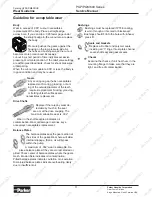
Guideline for acceptable wear

Body

Wear in excess of .005” cut-out necessitates  
replacement of the body. Place a straight-edge  
across bore. If you can slip a .005 feeler gage under 

the straight-edge in the cut-out area, replace 

the body.

Pressure pushes the gears against the 
housing on the low pressure side. As 
the hubs and bushings wear, the cut-out 

becomes more pronounced. Excessive  
cut-out in a short period of time indicates excessive 
pressure or oil contamination. If the relief valve settings 
are within prescribed limits, check for shock pressures 
or tampering. 
When the cut-out is moderate, 005” or less, the body is 
in good condition and may be reused.

Gears

Any scoring on gear hubs necessitates 

replacement. Scoring, grooving, or burr-

ing of the outside diameter of the teeth 

requires replacement. Nicking, grooving, 

or fretting of teeth surfaces also  

necessitates replacement.

Drive Shafts

Replace if there is any wear de-
tectable by touch in the seal  

area or at the drive coupling. The 

maximum allowable wear is .002”.

Wear in the shaft seal area indicates oil  

contamination. Wear or damage to splines, keys,  
or keyways necessitates replacement.

Balance Plates

The balance plates seal the gear section at 

the sides of the gears. Wear here will allow 

internal slippage, that is, oil will bypass 
within the pump.

A maximum of .002” wear is allowable. Re-

place balance plates if they are scored, eroded or 

pitted. Check center of balance plates where the gears 
mesh. Erosion here indicates oil contamination.

Pitted balance plates indicate cavitation or oil aeration.
Discolored balance plates indicate overheating, likely 
due to insufficient oil.

Bushings

Bushings must be replaced if PTFE coating  
is worn through or if scored or blackened. 

Bushings should fit into the bore with a heavy 

press fit.

Seals and Gaskets

Replace all rubber and polymer seals, 
including all “0” rings, thrust plate channel 

seals, shaft seal and gasket seals.

Checks

Examine the checks, if unit has them, in the 


  mounting flange to make sure that they are 


  tight, and free of contamination.

Catalog HY09-SM600/US

Wear Guideline

PGP/PGM600 Series
Service Manual

Topkitparts

Topkitparts

Topkitparts

Topkitparts

Topkitparts

Topkitparts

Topkitparts

Topkitparts

Topkitparts

Topkitparts
Topkitparts

Topkitparts

Topkitparts

Topkitparts

Topkitparts

Topkitparts

Topkitparts

Topkitparts
Topkitparts
Topkitparts
Topkitparts
Topkitparts

Topkitparts

Topkitparts

Topkitparts

Topkitparts

Topkitparts
Topkitparts

Topkitparts

Topkitparts

Topkitparts

Topkitparts

Topkitparts

Topkitparts

Topkitparts

Topkitparts

Topkitparts

Topkitparts

Topkitparts

Topkitparts

Topkitparts

Topkitparts

Topkitparts
Topkitparts

Topkitparts

Topkitparts

Topkitparts

Topkitparts

Topkitparts

Topkitparts

Topkitparts

Topkitparts

Topkitparts

Topkitparts

Topkitparts

Topkitparts

Topkitparts

Topkitparts

Topkitparts

Topkitparts

Topkitparts

Topkitparts

Topkitparts

Topkitparts

Topkitparts

Topkitparts

Topkitparts

Topkitparts

Topkitparts

Topkitparts

Topkitparts

Topkitparts

Topkitparts

Topkitparts

Topkitparts

Topkitparts

Topkitparts

Topkitparts

Topkitparts

Topkitparts

Topkitparts

Topkitparts

Topkitparts

Topkitparts

Topkitparts

Topkitparts

Topkitparts

Topkitparts

Topkitparts

Topkitparts

Topkitparts

Topkitparts

Topkitparts

Topkitparts

Topkitparts

Topkitparts

Topkitparts

Topkitparts

Topkitparts

Topkitparts

Topkitparts

Topkitparts

Topkitparts

Topkitparts

Topkitparts

Topkitparts

Topkitparts

Topkitparts

Topkitparts

Topkitparts

Topkitparts

Topkitparts

Summary of Contents for PGM 600 Series

Page 1: ...Service Manual PGP PGM600 Effective January 1 2012 Supersedes All Others Service Manual HY09 SM600 US PGP600 Series...

Page 2: ...ese products or systems the user through its own analysis and testing is solely responsible for making the final selection of the products and systems and assuring that all performance safety and warn...

Page 3: ...It is important to airblast all parts and wipe them with a clean lintless cloth before assembly USE CAUTION IN GRIPPING ALL PARTS IN THE VISE TO AVOID DAMAGING MACHINED SURFACES A pump must be driven...

Page 4: ...09 SM600 US PGP PGM600 Exploded View PGP PGM600 Series Service Manual ITEM QTY DESCRIPTION 1 1 Flange 2 1 Body 3 1 Drive Gear Shaft 4 1 Gear Driven 5 2 Screw Drive 6 4 Nut Hex 7 1 Name Plate 8 1 Ring...

Page 5: ...PGP PGM610 use a 1 00 25 4 mm dia bar x 3 25 long 82 55 mm for the PGP PGM620 use a 1 375 35 mm dia bar x 4 625 long 117 mm for the PGP PGM640 use a 1 00 25 4 mm dia bar x 4 625 long 117 mm The drawin...

Page 6: ...e drive shaft pointIng up Caution DO NOT GRIP ON OR NEAR ANY MACHINED SURFACES DURING ASSEMBLY OR DISASSEMBLY Match mark all sections Be sure to align these marks when reassembling 4 Remove the balanc...

Page 7: ...ft seal 9 Inspect all bushings for scoring or discoloration and replace if necessary Bushings cannot easily be removed with a puller We suggest replacing with a new flange or body with bushings alread...

Page 8: ...and an arbor press Be sure the that the grooves or seams are positioned as stated in Step 2 The bushings must be pressed into the bores flush with the casting face Be sure to support the castings so...

Page 9: ...e sleeve with grease to lubricate the shaft seal during assembly 13 Assemble the gears into the body journals and other contact faces should be oiled with clean hydraulic fluid The instructions for pr...

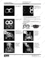
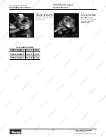
Page 10: ...cross corner Torque diagonally opposed fasteners to correct torque 16 Fit the mounting flange careful from the top down to the body Fit the interlocking track correctly Catalog HY09 SM600 US Assembly...

Page 11: ...wear de tectable by touch in the seal area or at the drive coupling The maximum allowable wear is 002 Wear in the shaft seal area indicates oil contamination Wear or damage to splines keys or keyways...

Page 12: ...on and minimize internal leakage Low viscosity leads to the following problems Higher leakage across all sealing gaps in the pump leading to lower volumetric efficiencies and heat Heat will cause loss...

Page 13: ...erature the longer the service life will be of the oil pump and other components Cold Weather Operation Oils for use in cold weather should have a viscosity not exceeding 7500 SUS 1620 cSt at the mini...

Page 14: ...ired by other components in the system High Water Base Fluids HWBF The use of 95 5 emulsion is not recommended Phosphate Ester Phosphate ester does not appear to effect pump perfor mance and service l...

Page 15: ...th clean oil to provide initial lubrication This is par ticularly important if the unit is located above the oil reservoir After connecting the lines and mounting the replacement unit operate the pump...

Page 16: ...y increase pressure on pump in 500 psi increments until the desired test pressure has been reached This should take about five minutes Delivery should run close to rated catalog performance figures wh...

Page 17: ...s in delivery of carriers or suppliers shortages of materials and any other cause beyond Seller s control 12 Entire Agreement Governing Law The terms and conditions set forth herein together with any...

Page 18: ...and global availability The Instrumentation Group is a global leader in the design manufacture and distribution of high quality critical flow components for worldwide process instrumentation ultra hi...

Reviews: