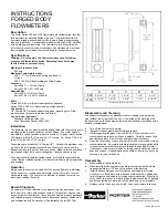
Description
The Porter Series F65 and F150 Flowmeters are variable area, low flow
rate indicators for metering liquids or gases. The meter consists of a
one-piece forged aluminum body with a tapered, fluted glass metering
tube and a ball float. A wrap around window shield allows 180° visibility
of the metering tube and scale. The flowmeter may be supplied with
our without a control valve and is available with stainless steel or brass
inserts (wetted parts) when the meter is used for corrosive service.
Specifications
Warning: Do not operate this flowmeter in excess of maximum
pressure and temperature limits. Exceeding these limits may
result in serious personal injury.
Maximum Pressure Limits
200 psig
Maximum Temperature Limits
160°F (71°C) w/Neoprene Packing and Buna-N
O-rings.
200°F (94°C) w/Viton Packing and Viton O-rings
Accuracy
Series F65: +/-10% Full Scale
Series F150: +/-5% Full Scale
Repeatability
Series F65: +/-0.5% Full Scale
Series F150: +/-0.25% Full Scale
Scale
Series F65: 0-65 mm (Direct reading scales optional)
Series F150: 0-150 mm (Direct reading scales optional)
Connections
1/8” Female NPT threaded adaptor with panel mounting nuts. Other
process connections available (consult factory).
Control Valve (Optional)
Standard Cartridge Valve (SC
)
High Resolution Control Valve (HR)
Operation
Slowly open the flow control valve until the desired flow rate is indicated
on the flowmeter. If equipped with integral control valve, turn counter-
clockwise to open. The center of the ball float is used as the reference
mark when reading the scale.
Installation
The flowmeter may be panel mounted and secured with the mounting nuts
provided on the inlet and outlet connection fittings. The meter must be
mounted in a vertical position to assure accuracy. To panel mount Series
F65 meters, drill two 9/16” holes on 4-1/2” centers. For Series F150, drill
two 9/16” holes on 8-13/16” centers.
Connections are horizontal, 1/8” female NPT. Connect the upstream sup-
ply line to the inlet (bottom) connection on the meter, and connect the
downstream line to the outlet (top) connection. Make certain connections
are clean and tight, but do not over tighten. Leak check prior to use.
If the metered fluid contains contaminants, it is highly recommended an
in-line filter be installed upstream of the meter to assure proper operation
and accuracy.
INSTRUCTIONS
FORGED BODY
FLOWMETERS
Disassembly and Cleaning
The flowmeter may easily be disassembled for cleaning or parts replace-
ment without removing it from the line. If the inside of the metering tube
requires cleaning, the tube may be removed and flushed or swabbed with a
suitable cleaning agent.
a.
Turn off the flow to the flowmeter.
b.
Squeeze sides of plastic front shield and remove.
c.
While supporting the glass tube, use a 5/32” Allen wrench and turn
counterclockwise to back out the seal spindle. Carefully remove tube
and float assembly. Remove tube seat packings if necessary.
d.
On all aluminum body meters, seal spindle may be removed by turning
counterclockwise. On meters with stainless steel or brass wetted parts,
turn seal spindle clockwise to remove through tube portion of meter.
e.
If necessary, remove control valve by turning counterclockwise with an
open-end wrench. Depending upon the width of the wrench, it may be
necessary to remove the knob.
Reassembly
a.
Make certain all parts are clean.
b.
When installing tube seat packings, stainless steel guide should pro-
trude approximately 1/16” above the surface of the packing.
c.
Install tube assembly and carefully tighten seal spindle by turning
clockwise. On flowmeters with brass and stainless steel wetted parts,
carefully tighten seal spindle by turning counterclockwise. When tight-
ening, check to make sure metering tube is properly seated on packing
and not contacting any metal part of the meter body or seal spindle.
d.
Replace control valve and front shield. Leak check before resuming
Return Shipments
If a flowmeter is to be returned to the manufacturer for any reason, con-
tact Porter for a return authorization number. This number must be refer-
enced on the return shipment. Items returned must be properly packaged
and shipped prepaid. Units exposed to hazardous gases or liquids must
be accompanied by a Declaration of Contamination Form (FM-768).
A B C D E
F65
5 9/16"
3 1/4"
1 3/16"
1 1/8"
4 1/2"
F150
9 15/16"
7 9/16"
1 3/8"
1 1/4"
8 13/16"
Dimensions shown are in Inches
FM-215 Rev. E 10/07


