192-011006N8 PSD1 Installation Guide
192-011006N8 2019-07
09.10.19 09:27
23 (109)
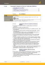
rated minimum 240 V (phase to ground), suitable for “Overvoltage Category III”,
and shall provide protection for a rated Impulse withstand Voltage peak of 4 kV.
2.10.5.3
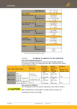
Tightening torque of the wiring terminals
Connector
Torque
mm
2
AWG
X17
Digital I/Os
Push-In
0,2 ... 1,5*
24-16
X51
DSL® feedback / motor brake
Push-In
0,2 ... 1,5*
24-16
X52
Motor
Push-In
0,2 ... 2,5**
26-12
X63
Mains supply / DC power
Push-In
0,2 ... 2,5**
26-12
*
max 0,75mm
2
ferrule with plastic sleeve
**
max 1,5mm
2
ferrule with plastic sleeve
2.10.5.4
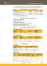
Auxiliary connection – electrical ratings
DC Bus Input / Output – X63
400 VDC / D.C. / 7 A
Auxiliary Input Supply – X17
Control Supply - Max 24 VDC
±
10% / max 0.5 ADC
Signal I/O’s Ports (PELV circuit) – X51
Signal I/O’s / Communication Ports - max 24 VDC / max 100 mA
2.10.5.5
Data of integrated dynamic brake unit
Internal DBU Ratings
Servo-Drive
Model Nos.
Max Current -
Amps
Max Duty Cycle -
per cent
Internal D.B.U.
Resistor
Ratings
Peak
rms
(Ohm)
PSD1SW1200
PSD1SW1300
7.84 A
0.1 A
1.27 % (@60s)
51
Ω
(40 W)
External DBU Ratings
Servo-Drive
Model Nos.
Max Current -
Amps
Max Duty Cycle -
per cent
Min Resistance
D.B.U. Resistor
Peak
rms
(Ohm)
PSD1SW1200
7.84 A
0.15 A
1.91 % (@60s)
51
Ω
(60 W)
PSD1SW1300
7.84 A
0.45 A
5.73 % (@60s)
51
Ω
(180 W)
2.10.5.6
In- / Output Ratings
Input Ratings
Servo-Drive
Model Nos.
Input Voltage
V AC
Frequency
Phase
Maximum Input Current
A rms
PSD1SW1200
3AC230 VAC
±
10 %
50/60 Hz
1.7
PSD1SW1300
4.2
PSD1SW1200
1AC230 VAC
±
10 %
50/60 Hz
6.8
PSD1SW1300
11.0
Output ratings
Device
Range of
Output
Voltage
VAC
Range of
Frequency
/ Phase
Output Current
Max. Continuous
Output Power
kW
Nominal
A rms
(Continuous)
Maximum
A rms
(Duty Cycle)*
PSD1SW1200
0-230 VAC
0-400 Hz
/
Three-Phase
2
6
0.64
PSD1SW1300
5
15
1.1
Note: * "Duty Cycle": 20% @10 s (ON=2.0 s - OFF=8.0 s)


